
Turn on suggestions
Auto-suggest helps you quickly narrow down your search results by suggesting possible matches as you type.
Showing results for
Please log in to access translation
Turn on suggestions
Auto-suggest helps you quickly narrow down your search results by suggesting possible matches as you type.
Showing results for
- Community
- Creo+ and Creo Parametric
- 3D Part & Assembly Design
- Create a point where two objects contact using pai...
Translate the entire conversation x
Please log in to access translation
Options
- Subscribe to RSS Feed
- Mark Topic as New
- Mark Topic as Read
- Float this Topic for Current User
- Bookmark
- Subscribe
- Mute
- Printer Friendly Page
Create a point where two objects contact using pairs clearance?
Feb 01, 2023
12:49 PM
- Mark as New
- Bookmark
- Subscribe
- Mute
- Subscribe to RSS Feed
- Permalink
- Notify Moderator
Please log in to access translation
Feb 01, 2023
12:49 PM
Create a point where two objects contact using pairs clearance?
I am using Creo 8
I am trying to determine the point where two objects contact each other. You can measure the value with pairs clearance, and it provides a point of contact, but you cannot do anything with that point. I would like to be able to take the point that it determines, and create a plane to measure the diameter where the objects are touching
Solved! Go to Solution.
Labels:
- Labels:
-
3D Animation
-
Assembly Design
ACCEPTED SOLUTION
Accepted Solutions
Feb 01, 2023
01:30 PM
- Mark as New
- Bookmark
- Subscribe
- Mute
- Subscribe to RSS Feed
- Permalink
- Notify Moderator
Please log in to access translation
Feb 01, 2023
01:30 PM
It would be helpful to observe the geometry involved here. If possible, post the models. What version of Creo are you working in?
I assume since you mention pairs clearance that you are in assembly mode when doing this. In assembly mode, create a quilt using the intersection of the components in question. This at a minimum would have surface area (and volume) of zero (a point contact) up to a max volume depending on the intersection of geometry.
Making some assumptions from your query:
Copy the surfaces of a body (each assembly component) for the two components intersecting.
Create a Boolean intersect of the two quilts to get the interference volume quilt.
You may also want to explore the use of field points and datum analysis features in this context depending on what you need to do here.
========================================
Involute Development, LLC
Consulting Engineers
Specialists in Creo Parametric
Involute Development, LLC
Consulting Engineers
Specialists in Creo Parametric
3 REPLIES 3
Feb 01, 2023
01:30 PM
- Mark as New
- Bookmark
- Subscribe
- Mute
- Subscribe to RSS Feed
- Permalink
- Notify Moderator
Please log in to access translation
Feb 01, 2023
01:30 PM
It would be helpful to observe the geometry involved here. If possible, post the models. What version of Creo are you working in?
I assume since you mention pairs clearance that you are in assembly mode when doing this. In assembly mode, create a quilt using the intersection of the components in question. This at a minimum would have surface area (and volume) of zero (a point contact) up to a max volume depending on the intersection of geometry.
Making some assumptions from your query:
Copy the surfaces of a body (each assembly component) for the two components intersecting.
Create a Boolean intersect of the two quilts to get the interference volume quilt.
You may also want to explore the use of field points and datum analysis features in this context depending on what you need to do here.
========================================
Involute Development, LLC
Consulting Engineers
Specialists in Creo Parametric
Involute Development, LLC
Consulting Engineers
Specialists in Creo Parametric
Feb 01, 2023
02:48 PM
- Mark as New
- Bookmark
- Subscribe
- Mute
- Subscribe to RSS Feed
- Permalink
- Notify Moderator
Please log in to access translation
Feb 01, 2023
02:48 PM
I am using Creo 8.
Trying the copy surfaces and intersection method works, but it sometimes fails when there is 0 clearance (possible bug, because it works if I save the problematic assembly as a copy and try again). But otherwise it does work.
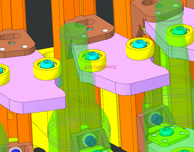
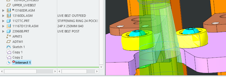
I am curious to know if there is an alternate method. The ultimate goal is to know the diameter where the container touches on the rollers at the top. I attached a zip file with the assembly I am looking at. I was able to create the point at the top of the interference oval and use that for a diameter (sketch 1) and measurement
Thanks for your help!
Feb 01, 2023
04:30 PM
- Mark as New
- Bookmark
- Subscribe
- Mute
- Subscribe to RSS Feed
- Permalink
- Notify Moderator
Please log in to access translation
Feb 01, 2023
04:30 PM
I do not have Creo 8 installed, still working in 7 but I understand the problem now.
For an analysis to determine the answer based on nominal dimensions of the components you can do it in part mode using the bottle model. You can determine the diameter of contact circle between the rollers analytically or by drawing a planar circle tangent to both rollers at the plane of largest roller diameter. This will be the target value (diameter) to use in a feasibility/optimization study in the bottle part model.
If you have behavioral modeling license (BMX) this will be fully automated using the following steps.
BMX reference link:
In the bottle part model do the following (assuming a section normal to the height of the bottle is circular):
- Create a plane offset in the vertical direction such that it can be moved along the neck/body of the bottle by changing the offset value.
- Using this plane, create a curve of intersection between this plane and the outer surface of the bottle geometry.
- Create a measure analysis feature to measure the diameter of the intersection curve.
- Create a feasibility/optimization study and set the goal to match the target diameter derived from the measure of the roller geometry.
- Run the feasibility analysis: This will set the height of the offset plane to match the target diameter.
Without BMX module you will need to manually iterate the offset datum plane value (step 1) until you get the target value for the diameter.
========================================
Involute Development, LLC
Consulting Engineers
Specialists in Creo Parametric
Involute Development, LLC
Consulting Engineers
Specialists in Creo Parametric


