Community Tip - Have a PTC product question you need answered fast? Chances are someone has asked it before. Learn about the community search. X
- Community
- Creo+ and Creo Parametric
- 3D Part & Assembly Design
- Re: Create constant curve length loops
- Subscribe to RSS Feed
- Mark Topic as New
- Mark Topic as Read
- Float this Topic for Current User
- Bookmark
- Subscribe
- Mute
- Printer Friendly Page
Create constant curve length loops
- Mark as New
- Bookmark
- Subscribe
- Mute
- Subscribe to RSS Feed
- Permalink
- Notify Moderator
Create constant curve length loops
I am working with lifting equipment and need to model lifting slings. Creating a straight lifting sling is very simple when using the circumference dimension and letting the centre-centre distance be variable. See the picture below.
The challenge is creating a similar sling, but with a 90° twist. I have tried the pipe feature, sweep and swept blend, but I haven't succeded in creating is as one feature. It is possible to create it with two features, but it isn't very elegant. See the attached model.
Is there an elegant way to create a twisted sling? And is it possible to control the curve length and keep it constant?
Looking forward to some good ideas.
/Niels
This thread is inactive and closed by the PTC Community Management Team. If you would like to provide a reply and re-open this thread, please notify the moderator and reference the thread. You may also use "Start a topic" button to ask a new question. Please be sure to include what version of the PTC product you are using so another community member knowledgeable about your version may be able to assist.
- Labels:
-
2D Drawing
- Mark as New
- Bookmark
- Subscribe
- Mute
- Subscribe to RSS Feed
- Permalink
- Notify Moderator
ya its ok
- Mark as New
- Bookmark
- Subscribe
- Mute
- Subscribe to RSS Feed
- Permalink
- Notify Moderator
Maybe you have already tried this, but well...
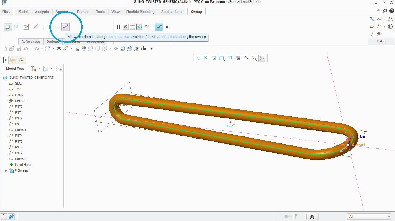
You are able to create that using only two features. Define the curve and then use a Sweep feature. But! You will have to press the button shown in the picture in order create a succeed sweep. Otherwise, it won't work. For keeping the curve length constant, I don't know the answer 😃

- Mark as New
- Bookmark
- Subscribe
- Mute
- Subscribe to RSS Feed
- Permalink
- Notify Moderator
Hi,
if I understand you well the root of the problem is How to get 3D curve with specific length ?. I think you can solve this problem, but the solution is little bit complicated.
My suggestion:
- create parameters
- create analysis feature
- create annotation showing values in graphics window
- create relations
- create mapkey running regeneration 10-times (or 100-times ...) to speed up the process
For inspiration see attached model. The problem solved in it is What is the water level height, when the bottle contains 1 litter of water ?
Info related to my model (created in CR2 M070):
- set MYSTART value to 2, if you want to modify dimensions manually
- set MYSTART value to 1, when you want to start iterations
- regenerate model to get another step
MH
Martin Hanák
- Mark as New
- Bookmark
- Subscribe
- Mute
- Subscribe to RSS Feed
- Permalink
- Notify Moderator
About your model twisted i see there's not tangency in some points and with curves you don't have total control of transition of guide curve.
Take a look at attached model.
- Mark as New
- Bookmark
- Subscribe
- Mute
- Subscribe to RSS Feed
- Permalink
- Notify Moderator
There are a lot of variables not known to come up with an accurate answer.
If an approximation is sufficient, here goes:
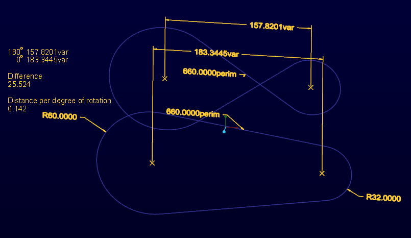
(d1) Make the sketch with the perimeter measure as before and note the distance between the axes of the end radii.
(d2) Now make the sketch with a cross-over to represent 180 degree rotation and again, note the distance of the axes at the end radii.
You can use the distance as a linear interpolation of the difference between the two noted values (d1-d2=d3), assigning 1/180th of the difference (d3) to each degree of rotation.

With the value between axes and the angle, you have the motion path for the secondary axis.
Of course, if that leaves another degree of freedom for the secondary axis, the error will increase, but not by much if the position is essentially the same.
Again, accurate models are not nearly as easy to obtain but this method can be broken down into more and more relevant data.
Now would be a good time to have a 3D sketch available in Creo like they have in SolidWorks ![]()
- Mark as New
- Bookmark
- Subscribe
- Mute
- Subscribe to RSS Feed
- Permalink
- Notify Moderator
I'd suggest using an evaluate curve as part of your solution. Or maybe a wrap? Unlike a project, it should keep the curve length constant. This looks fun, and I'd LOVE to look at it....but they had yet another round of layoffs the other day...... ![]()
Best of luck!


