
Turn on suggestions
Auto-suggest helps you quickly narrow down your search results by suggesting possible matches as you type.
Showing results for
Please log in to access translation
Turn on suggestions
Auto-suggest helps you quickly narrow down your search results by suggesting possible matches as you type.
Showing results for
Community Tip - You can Bookmark boards, posts or articles that you'd like to access again easily! X
- Community
- Creo+ and Creo Parametric
- 3D Part & Assembly Design
- Re: Creating Angled Hole with Counterbore
Translate the entire conversation x
Please log in to access translation
Options
- Subscribe to RSS Feed
- Mark Topic as New
- Mark Topic as Read
- Float this Topic for Current User
- Bookmark
- Subscribe
- Mute
- Printer Friendly Page
Creating Angled Hole with Counterbore
Sep 11, 2012
09:07 PM
- Mark as New
- Bookmark
- Subscribe
- Mute
- Subscribe to RSS Feed
- Permalink
- Notify Moderator
Please log in to access translation
Sep 11, 2012
09:07 PM
Creating Angled Hole with Counterbore
Hi,
First, I'm not sure if this is the correct place to post, as the community is "Creo" and I am running WF 3. However, I cannot find the WF 3 community, so if this is not the place, please point me in the right direction.
Anyway, I am trying to create a hole at an angle to a surface. The hole is also to be counter bored. I am having great difficulty doing this - I have been able to create a hole by creating an extra axis & datum plane, but it is a simple hole. When I try to change the type of hole from "simple" to "standard" (which is the only place the Counterbore option exists), it does not work (the counterbore is never on the proper surface).
Attached is a 2D sketch of what I am trying to do.
Any help would be appreciated.
This thread is inactive and closed by the PTC Community Management Team. If you would like to provide a reply and re-open this thread, please notify the moderator and reference the thread. You may also use "Start a topic" button to ask a new question. Please be sure to include what version of the PTC product you are using so another community member knowledgeable about your version may be able to assist.
Solved! Go to Solution.
ACCEPTED SOLUTION
Accepted Solutions
Sep 12, 2012
12:31 AM
- Mark as New
- Bookmark
- Subscribe
- Mute
- Subscribe to RSS Feed
- Permalink
- Notify Moderator
Please log in to access translation
Sep 12, 2012
12:31 AM
Sometimes pictures are much better. They work great here in PlanetPTC... when they work 
So this is pretty much what you did in WF3 - It is a counterbored hole feature attached to a datum plane. I did not define an axis for location.
From there, I used the center axis to pattern the holes -

Now this is the same hole as a revolve... and no "placement plane" -

...and it patterns the very same way as the hole did.
Pictures are nice, huh 
16 REPLIES 16
Sep 11, 2012
09:15 PM
- Mark as New
- Bookmark
- Subscribe
- Mute
- Subscribe to RSS Feed
- Permalink
- Notify Moderator
Please log in to access translation
Sep 11, 2012
09:15 PM
These are much easier to define as revolve features.
Think about how the hole has to think about the depth of the counterbore. It needs a perpendicular face to define it.
Technically, I would agree that the depth could be a point in the center where the axis intersects the surface but that is not how holes are defined in WF.
This forum is fine for WF3 users too
Sep 11, 2012
09:40 PM
- Mark as New
- Bookmark
- Subscribe
- Mute
- Subscribe to RSS Feed
- Permalink
- Notify Moderator
Please log in to access translation
Sep 11, 2012
09:40 PM
Antonius,
Thank you for your reply. However, if I have a bunch of holes to do, w/ varying diameters & counter bores, are you suggesting that I create revolve features for each of these? That seems very tedius to me, not to mention the fact that, shouldn't that be what the "hole" feature is for?
How would I create the revolved feature? Would I create it on a plane that is normal to the surface I'm wanting to cut the hole into? This seems confusing to me.
Anyway, after I posted my original question, I think I *sort* of was able to figure it out. It's not the most elegant solution, and due to the issues cited below, I'm not sure if it will work for my application.
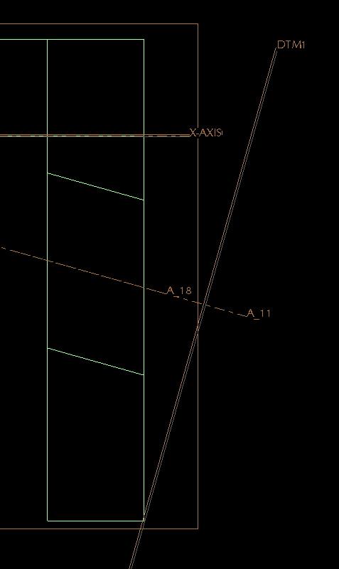
Attached are 2 screenshots of my Pro/E model in wireframe mode. The first attachment shows how I got the (simple) hole at the angle I want. Even this seems tedious to me - so Pro/E forces me to create a whole new axis, and a whole new plane - just to create ONE simple hole??
Why can't I just pick the surface I want the hole to be in, locate it from the surfaces where I want it, then have an option to drill normal to that surface, or to drill at "X degree" angle to that surface? <-------Possible feature request!!!! 
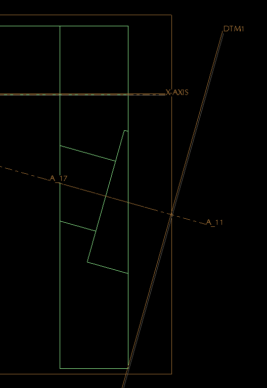
Anyway, the 2nd attachment shows the hole after I converted it to a "standard" hole (the only way I could get the Counter Bore functionality to show up). Now, one thing I'm not sure about is - does Pro/E still think there are threads in this hole (I'd like it to be a non-threaded THRU hole). Also, it is forcing me to choose a drill & thread size (ie, 10-24), which I do NOT want.
This is why I don't think this will work for me, as I do NOT want to be forced to use a UNC/UNF/ISO standard drill sized hole. Why doesn't Pro/E allow me to create a SIMPLE (ie, non-threaded) hole w/ a counter bore? Surely I am not the only person who has ever needed to do this? The hole is to be used to insert a liner bushing, then insert a slip-renewable bushing inside the liner bushing - this is not something which I would consider atypical.
Finally, as I was typing this, I thought of yet another option. Keep my original simple hole. Then create another hole w/ a larger diameter which is coaxial to the 1st hole. I could specify the depth I want the 2nd hole to go to (hence, "faking" a counterbore).
Please tell me that this is easier in Creo?? Please!! 
Thanks,
Rob
Message was edited by: Robert Brookover
Sep 11, 2012
11:43 PM
- Mark as New
- Bookmark
- Subscribe
- Mute
- Subscribe to RSS Feed
- Permalink
- Notify Moderator
Please log in to access translation
Sep 11, 2012
11:43 PM
True, you have found the "normal" surface by defining the datum plane. However, creating the axis was optional although you do need features to be able to locate the hole in relation to the part, so the axis serves a useful purpose.
I am not 100% at WF3... I may not even be 15% as I only used it for about 3 months. But in Creo, the thread, vs non-thread, and special applications are a lot simpler. But as far as locating it, not really. You still need that "perpendicular surface" feature.
A hole in any of the Creo apps, Pro/E, WF, or Creo is still a revolve feature. It works with a planer sketch, is revolves about a primary (dedicated) centerline which becomes an axis. By calling it a hole, it simply does a lot of things behind the scenes. One of those things is the ability to tie a "cosmetic thread" feature to the hole. And these are simply defined by tables that have some presets in them for making some "curve" features that "represent" a thread and provides some smarts for detailing them in drawings.
So this will come around on you as you say that making the hole feature is easier than making lots of revolves; yet each hole still needs a normal plane for location. In the revolve, you could have left out the datum plane and used reference geometry to define the angle... and this method is very -not- unlike simply creating a hole from an -internal- sketch where you can make any size and shape hole you please; except that a hole created with a sketch -still- requires the normal "surface' to place the hole.
So the root of your question is, how do I make this easy on myself, and this is where I get lost due to my lack of WF3 knowledge. I use to use Pro/E 2000i for years and am now using Creo 2.0. Patterns in this case, yours and mine, are your friend. I know patterns are very powerful and have become more-so in the later releases. One of the most powerful additions to patterns is the ability to now pattern based on an axis. I don't know if WF3 has this yet. Regardless, it is patterning that will make your choice on how you want to make the holes work for you.
I have more often than not been thwarted by angular holes just like these. I do often opt for the simple "revolve" method. When I have several holes that I cannot pattern easily, or when the pattern functionality simply fails me over and over again... I just save the sketch and when I create the next hole, simply open the section file and use it for the second hole. Later I will create the relations to make all the whole follow the original instance.
So the tool is powerful enough, but the way of thinking is still the same as original Pro/E. Depending on what you are trying to achieve, it may even be useful to an actual planer surface for the holes and later trim the surface instead. Again, it is about planning your "history" based model. If you challenged the body of this forum with the most efficient way to achieve what you want to achieve, you will likely get a different answer, and perspective from each user. My latest find in Creo 2.0?... Creating a pattern using a sketch with datum points! It rocks
Are you planning an upgrade to Creo 2.0 anytime soon?
Sep 12, 2012
12:31 AM
- Mark as New
- Bookmark
- Subscribe
- Mute
- Subscribe to RSS Feed
- Permalink
- Notify Moderator
Please log in to access translation
Sep 12, 2012
12:31 AM
Sometimes pictures are much better. They work great here in PlanetPTC... when they work
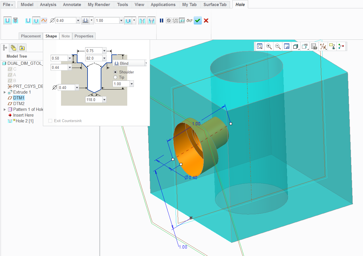
So this is pretty much what you did in WF3 - It is a counterbored hole feature attached to a datum plane. I did not define an axis for location.
From there, I used the center axis to pattern the holes -
Now this is the same hole as a revolve... and no "placement plane" -
...and it patterns the very same way as the hole did.
Pictures are nice, huh
Sep 13, 2012
12:32 PM
- Mark as New
- Bookmark
- Subscribe
- Mute
- Subscribe to RSS Feed
- Permalink
- Notify Moderator
Please log in to access translation
Sep 13, 2012
12:32 PM
Antonius,
Thank you for responding. WF 3 is a bit different than what your screen shots show, and I have not found a way to use the Hole tool to give me a Counter Bore hole with my own diameter (it wants to force me to use pre-defined UNC / UNF / ISO standards w/ threads), but I get the gist of what you are trying to convey w/ the Hole feature vs the Revolve feature.
My opinion is that creating a hole at an angle is "clunky" in Pro/E because I don't feel you should have to create an external Datum just to make a hole (I still maintain that there should be an option to place the hole Normal to, or at any angle to the surface you want), but that's just my opinion.
At any rate, I have marked this question as "Answered" as per your last post.
Thank you,
Rob
Sep 13, 2012
01:00 PM
- Mark as New
- Bookmark
- Subscribe
- Mute
- Subscribe to RSS Feed
- Permalink
- Notify Moderator
Please log in to access translation
Sep 13, 2012
01:00 PM
It's not as easy as specifying an angle, because there are two angles involved. One angle is the true angle between the axis of the hole and the surface the hole goes into. The other angle is a clocking angle for the true angle. That is, it's possible to drill any number of holes that are 30 degrees to a surface through a point, but which of them do you want? Towards the upper side, right, left, somewhere between left and up?
That's what the normal plane definition does, it sets those two angles for the feature.
As for repeated revolves - make one and then use copy and paste to add the others. Or create a UDF.
Sep 13, 2012
01:18 PM
- Mark as New
- Bookmark
- Subscribe
- Mute
- Subscribe to RSS Feed
- Permalink
- Notify Moderator
Please log in to access translation
Sep 13, 2012
01:18 PM
David; indeed the definition may get confusing, but providing a drag handle to "force" an angle planer to the intent placement surface isn't beyond possibilities.
Sep 13, 2012
02:11 PM
- Mark as New
- Bookmark
- Subscribe
- Mute
- Subscribe to RSS Feed
- Permalink
- Notify Moderator
Please log in to access translation
Sep 13, 2012
02:11 PM
A more user-intuitive interface can be designed. As I said, I do not know if Creo has changed the interface for certain features / actions, but there are a number of things in Pro/E WF 3 & WF 4 that are unnecessarily complicated (ie, the cabling feature, holes, etc).
When folks complain over & over & over about how difficult it is to do something, the software developers should take that as a hint that it is too complicated. And a quick search though these forums shows question after question about how to do something which should be trivial. A mechanical designer shouldn't have to spend more time figuring out how the software wants you to do something than he does actually designing the product in the first place.
I'm not bashing Pro/E, but to be told that it's "complicated" to cut a hole into a surface seems to me to be a cop-out, or an overly-ambitious attempt at defending a poorly designed interface.
If I want to drill a hole, I should be able to pick the surface I want to drill it on, then set the diameter, the depth, and an angle (or even 2 angles, the "clocking angle" you were referring to), whether or not I want a CB or threads, and have it do it.
Even doing it the way Pro/E wants us to do it, which is to create a whole new datum, is unnessarily complicated - because if I have a surface, and then I have to create a datum at an angle to that surface, and then I have to choose that datum to start the hole - well, there's a "gap" of some angle between the surface & the datum, and Pro/E forces me to start the hole from that datum, go through the invisible "gap" and into the surface. So if I want to drill a hole that is 1" deep into the surface, I now have to figure out how much to add to that 1" (based off of the sin/cosine of the angle of the Datum) in order to get it to to be 1" into the surface because I'm not simply cutting a hole from the surface, I'm forced to cut the hole from the datum, through air, and then into the surface. That's ridiculous.
This isn't circa 1998 and we're not running I-DEAS. There are plenty of other CAD tools out there w/ better user interfaces, perhaps the developers can take cues from them. To tell folks to make a revolve is a cop-out, because why is there a "hole" feature in the first place then? Why don't I just start making "cut" tools like I used to do when I ran I-DEAS 10+ years ago?
Sep 13, 2012
02:51 PM
- Mark as New
- Bookmark
- Subscribe
- Mute
- Subscribe to RSS Feed
- Permalink
- Notify Moderator
Please log in to access translation
Sep 13, 2012
02:51 PM
<soapbox on>
Funny... this is the prevailing question throughout the ages for PTC.
One assumes the developers actually read the forums. In fact, I highly doubt they do. Very common among industry where developers; hardware, software, gadgets... ever join forums except to quell an uprising that affects the bottom line. There are only rare few forums where the developers actually participate in regular discussions. PTC simply has way to much on their plate to care about their core. There is no "profit" in giving the core more functionality.
I find it odd that we have to have current maintenance to submit ideas to PTC... moreover, we have to twist the arms of customer service to report issues to developers through escalations! If you are not an uber customer, the only way you can submit a product enhancement is to either apply to be part of an active committee, or post an idea in the forum... which only gets emailed to people that seem to always be on vacation.
<soapbox off>
The idea of revolving a "hole"... rather, making a revolve feature to create a hole is actually much more powerful than the "simple" hole feature. Having been trained to use model dimensions in detailing, I can make much more comprehensive hole details with revolve that use actual references needed in the drawing.
Creo went one better in adding dedicated "datum" centerlines separate from geometry centerlines. This had always been a shortcoming in that you could only use one centerline (reliably) in a revolve sketch. Now you can use many centerlines as long as you have one "datum" centerline to ensure the revolve is consistent.
The hole feature has gotten better but it is still archaic in that it uses hole tables that are poorly formatted and even more mysterious to new users. I find that in Creo, it has improved enough that it is helpful for truly associative drawings. Still, there are improvements to the interface for hole call-out annotation that could be made.
Having been seasoned in Pro/E, I see nothing I haven't seen before. Things are just a bit more verbose than before. I'm really glad I didn't have to suffer through the WF introduction.
Sep 13, 2012
01:12 PM
- Mark as New
- Bookmark
- Subscribe
- Mute
- Subscribe to RSS Feed
- Permalink
- Notify Moderator
Please log in to access translation
Sep 13, 2012
01:12 PM
Interesting about the hole being related to a thread size. When using counterbores, this is almost always a clearance hole. So they must be asking what size screw the clearance is for. There are tables that control standardized clearance holes for industry standard thread sizes.
I suspect they expect you to make an internal sketch for any "custom" hole size in WF3. In this sense, Creo has improved significantly.
If you make the hole using the thread size near the size you want, can you edit the diameter after the fact?
I often have to place holes on an angle conical surfaces. Revolve is probably the only way to make these short of making a tangent datum plane. The good thing about making datum planes is that you can use one of the datum's location dimensions for further patterning.
I still remember the 1st time I had to create a hole on a conical surface back in the short-lived lightweight Pro/E "Designer". Yea... clunky barely describes it
Sep 13, 2012
02:02 PM
- Mark as New
- Bookmark
- Subscribe
- Mute
- Subscribe to RSS Feed
- Permalink
- Notify Moderator
Please log in to access translation
Sep 13, 2012
02:02 PM
Antonius,
The holes are for bushings, which are press fit, and so they do not need threads. They are also drilled at an angle to the surface, which is why a counter bore is needed (otherwise, the "head" of the bushing will interfere w/ the surface because the bushing goes into the surface at an angle, and not normal to the surface).
Sep 13, 2012
02:32 PM
- Mark as New
- Bookmark
- Subscribe
- Mute
- Subscribe to RSS Feed
- Permalink
- Notify Moderator
Please log in to access translation
Sep 13, 2012
02:32 PM
Aha... so I opened a WF3 session to see what you are looking at. Indeed, the only way to make a counterbore is to specify a thread. Definitely an oversight!
Yes, you want to go to the hole feature and under "placement", change "simple" to "sketched" and click the sketch button on the right. Draw a centerline and define half the hole.
Remember you can get a diameter dimension in sketch by clicking the line-centerline-line when creating a dimension.
Next, you can define the datum placement plane while creating the hole feature. Just click on the datum plane feature button and create it. This way, the sketch and datum plane all become part of the hole feature.
I never much liked the WF3 interface... now I remember why.
I understand your application. Threads should have nothing to do with this.
Sep 14, 2012
01:51 AM
- Mark as New
- Bookmark
- Subscribe
- Mute
- Subscribe to RSS Feed
- Permalink
- Notify Moderator
Please log in to access translation
Sep 14, 2012
01:51 AM
Hi Robert... just FYI....
The only way to specify the counterbore back at WF3 was to turn on the standard hole. That brought along the drop-down box to pick a thread size but this does not automatically make the threads. If this bothers you, it's very easy to make a new hole chart for common holes requiring a counterbore. You're just picking a thread series for a clearance hole. If you don't like the defaults, make one that suits you.
At WF3 you're a bit stuck to come up with a better solution. However, at WF5 and then again at Creo, we've been given better datum placement tools. You can drop a coordinate system on a surface and use either linear or radial dimensions to locate it. From there, you could drop a UDFto create the holes with a table of common counterbore sizes embedded in it.
If this UDF were created with enough foresight, you'd have a counterbored hole with some preset sizes- but also with the ability to enter arbitrary numbers for the hole and cbore diameters. In addition, you might try to incorporate a spherical coordinate system into the UDF to create a hole feature capable of 'gimbal-like' movements.
These features would be pattern-able, too.
There are quite a few variables to consider when trying to make a hole like this. I'm not sure it's necessarily fair to hack on PTC for not listening to customers regarding holes when we're talking about a piece of software four revisions old. There have been improvements in the interim. That's not to say I don't have a list of improvements to submit that are a mile long or that *I* don't routinely call out PTC when I think they're dropping the ball. In this case though, I think we're talking about an infrequently used option that probably wouldn't be very easy to operate no matter what improvements you made to the interface.
Sep 14, 2012
04:21 AM
- Mark as New
- Bookmark
- Subscribe
- Mute
- Subscribe to RSS Feed
- Permalink
- Notify Moderator
Please log in to access translation
Sep 14, 2012
04:21 AM
Hi all,
there is a config option, hole_diameter_override, set this to yes & you can modify your hole sizes away from the standard. Hope this helps.
John
Sep 14, 2012
12:59 PM
- Mark as New
- Bookmark
- Subscribe
- Mute
- Subscribe to RSS Feed
- Permalink
- Notify Moderator
Please log in to access translation
Sep 14, 2012
12:59 PM
john pryal wrote:
Hi all,
there is a config option, hole_diameter_override, set this to yes & you can modify your hole sizes away from the standard. Hope this helps.
John
What -will- they think of next Thanks for the tip, John.
Sep 14, 2012
03:40 PM
- Mark as New
- Bookmark
- Subscribe
- Mute
- Subscribe to RSS Feed
- Permalink
- Notify Moderator
Please log in to access translation
Sep 14, 2012
03:40 PM
Nice, I always thought the diameter of clearance of the standard hole can't be changed.
Good to finally know I was wrong. Thanks.


