
Turn on suggestions
Auto-suggest helps you quickly narrow down your search results by suggesting possible matches as you type.
Showing results for
Please log in to access translation
Turn on suggestions
Auto-suggest helps you quickly narrow down your search results by suggesting possible matches as you type.
Showing results for
Community Tip - Stay updated on what is happening on the PTC Community by subscribing to PTC Community Announcements. X
- Community
- Creo+ and Creo Parametric
- 3D Part & Assembly Design
- Re: Creo 2.0 - Attaching to Dimensions (Geo. Tol.,...
Translate the entire conversation x
Please log in to access translation
Options
- Subscribe to RSS Feed
- Mark Topic as New
- Mark Topic as Read
- Float this Topic for Current User
- Bookmark
- Subscribe
- Mute
- Printer Friendly Page
Creo 2.0 - Attaching to Dimensions (Geo. Tol., notes, etc.)
Aug 20, 2013
01:48 PM
- Mark as New
- Bookmark
- Subscribe
- Mute
- Subscribe to RSS Feed
- Permalink
- Notify Moderator
Please log in to access translation
Aug 20, 2013
01:48 PM
Creo 2.0 - Attaching to Dimensions (Geo. Tol., notes, etc.)
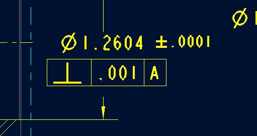
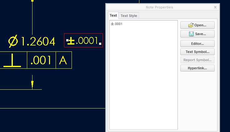
I'm having trouble figuring out how to relate feature control frames and notes to dimensions as in the screen shot below. I was wondering if someone knew how the guy before me did it. The feature control frame is placed as a free note, but is somehow related to the dimension. The dimension allows room for it, and moves with it.
Thanks in advance,
Matt
This thread is inactive and closed by the PTC Community Management Team. If you would like to provide a reply and re-open this thread, please notify the moderator and reference the thread. You may also use "Start a topic" button to ask a new question. Please be sure to include what version of the PTC product you are using so another community member knowledgeable about your version may be able to assist.
Labels:
- Labels:
-
2D Drawing
10 REPLIES 10
Aug 20, 2013
01:57 PM
- Mark as New
- Bookmark
- Subscribe
- Mute
- Subscribe to RSS Feed
- Permalink
- Notify Moderator
Please log in to access translation
Aug 20, 2013
01:57 PM
Check Antonius answer in this thread and see if this is how it was done.
http://communities.ptc.com/message/211788#211788
Thanks, Dale
If your in the annotate tab, right click on the dimension and them go to dsiplay.
You may see @[perp symbol]@[.0001@]@[A@]
Aug 20, 2013
02:08 PM
- Mark as New
- Bookmark
- Subscribe
- Mute
- Subscribe to RSS Feed
- Permalink
- Notify Moderator
Please log in to access translation
Aug 20, 2013
02:08 PM
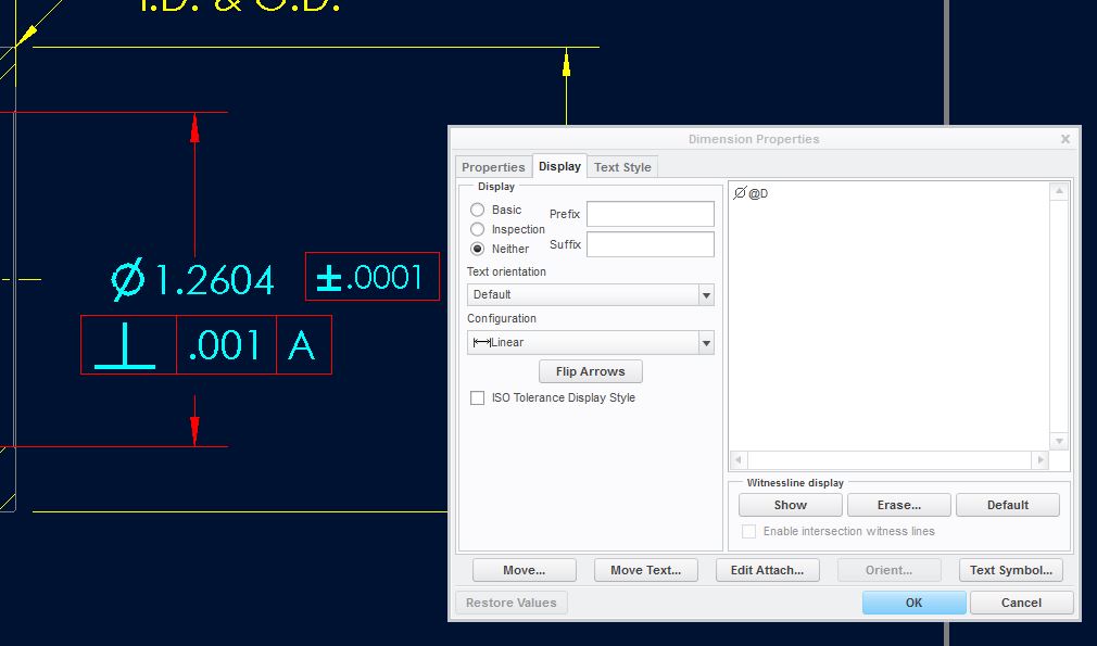
It is appended text to the dimension, Matt. In the last tab of the dimension properties dialog is a multiline text editor. Open the Symbol pallete to select symbols. Each box entry needs to be delimited with @[ and @].
Aug 20, 2013
03:47 PM
- Mark as New
- Bookmark
- Subscribe
- Mute
- Subscribe to RSS Feed
- Permalink
- Notify Moderator
Please log in to access translation
Aug 20, 2013
03:47 PM
These are all separate features. The dimension is it's own feature driven from the model. The +/-.0001 is a note, the feature control frame is it's own feature also. Editing it brings up the geo. tol. properties box. Thanks though.
Matt
Aug 20, 2013
08:15 PM
- Mark as New
- Bookmark
- Subscribe
- Mute
- Subscribe to RSS Feed
- Permalink
- Notify Moderator
Please log in to access translation
Aug 20, 2013
08:15 PM
It is always hard to know what you are looking at when you see it on a drawing.
The .0001 tolerance really should have been a tolerance as part of the dimension. If you don't know to change the detail config to show tolerances, people tend to just type it in.
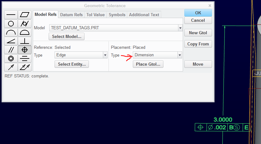
The feature control block can be "attached" to the dimension through the GTOL dialog. But again, you have to know how to properly define the datums and the GTOL features in the model (or as drawing features) to attach them to the dimension.
Aug 20, 2013
08:28 PM
- Mark as New
- Bookmark
- Subscribe
- Mute
- Subscribe to RSS Feed
- Permalink
- Notify Moderator
Please log in to access translation
Aug 20, 2013
08:28 PM
The option is not always available as it is dependent on the tolerance type that is selected but when it is available, you will have the option to attach the GTOL to the dimension using the GTOL properties dialog.
Aug 21, 2013
07:29 AM
- Mark as New
- Bookmark
- Subscribe
- Mute
- Subscribe to RSS Feed
- Permalink
- Notify Moderator
Please log in to access translation
Aug 21, 2013
07:29 AM
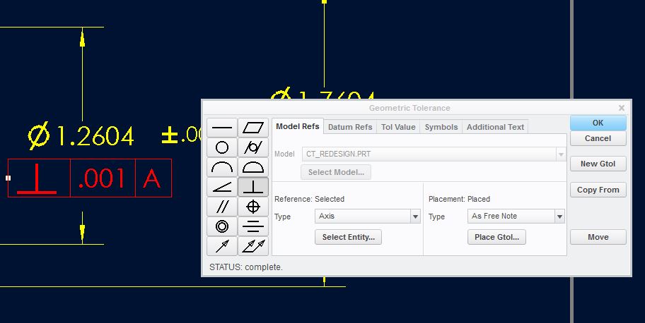
Thanks. I really struggle with attaching feature control frames to dimensions so I never do it. They seem to become part of the dimension and I can never detach them again. I will find out how this was done sometime. To me, these are definately independent from the screen snips below...
Thanks for the help everyone.
Matt
Aug 21, 2013
11:56 AM
- Mark as New
- Bookmark
- Subscribe
- Mute
- Subscribe to RSS Feed
- Permalink
- Notify Moderator
Please log in to access translation
Aug 21, 2013
11:56 AM
True, the control frame attached to a dimension seems to be harder to pick. I can pick it on the Drawing Tree when the Annotation tab is active.
In general, your example is simply a messy way of using the detail package. I've seen this done when contractors are not familiar with the tool and they just make the drawing "look" good. I do my fair share of cheating things onto drawings but I do consider this one extreme.
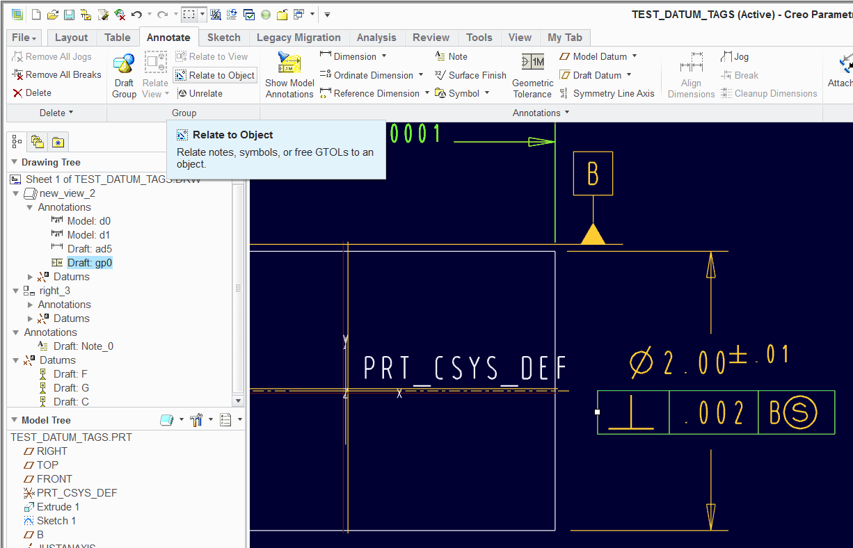
Back to your original question, they used the "relate to object" feature. The dimension probably has a couple of space characters below the @D in the text to make room in between the leaders. Then the tol block was related to the dimension. Now they move together. Similar to "relate to view".
Aug 21, 2013
08:39 PM
- Mark as New
- Bookmark
- Subscribe
- Mute
- Subscribe to RSS Feed
- Permalink
- Notify Moderator
Please log in to access translation
Aug 21, 2013
08:39 PM
Thanks Antonius, I'll have to look for the "relate to object" feature as I've never seen it, just "relate to view". It may help with revision balloons. Knowing that I can edit the feature control frame after it's attached to a dimension makes me a lot more comfortable about using it. I'll look around tomorrow and try to put it to work.
I can't thank everyone enough for their help. It's taken so much frustration away trying to learn Creo on my own.
Matt
Aug 22, 2013
08:59 AM
- Mark as New
- Bookmark
- Subscribe
- Mute
- Subscribe to RSS Feed
- Permalink
- Notify Moderator
Please log in to access translation
Aug 22, 2013
08:59 AM
You should be able to edit the feature control frame attached to a dimension in the drawing by using the smart filter or using query select. By default, it will always select the dimension first. Also, I believe once you select the dimension, if you then hover over the frame, it will then let you easily select the frame.
Using the smart filter set to Geometric Tolerance setting while in the annotation tab, you can also get it to select the frame and you should be able to right click properties and edit the feature control frame.
Hope this helps,
Steve
Aug 22, 2013
11:41 AM
- Mark as New
- Bookmark
- Subscribe
- Mute
- Subscribe to RSS Feed
- Permalink
- Notify Moderator
Please log in to access translation
Aug 22, 2013
11:41 AM
Thanks Steve. There is so much I have to learn in Creo. I also keep forgetting about the to "pick from list" right click option. That works well for this. I'll give your suggestion a try too.
Matt


