Community Tip - Did you know you can set a signature that will be added to all your posts? Set it here! X
- Community
- Creo+ and Creo Parametric
- 3D Part & Assembly Design
- Re: Creo Drawing....Cleanup Dimension Issues for d...
- Subscribe to RSS Feed
- Mark Topic as New
- Mark Topic as Read
- Float this Topic for Current User
- Bookmark
- Subscribe
- Mute
- Printer Friendly Page
Creo Drawing....Cleanup Dimension Issues for diametrical dimensions
- Mark as New
- Bookmark
- Subscribe
- Mute
- Subscribe to RSS Feed
- Permalink
- Notify Moderator
Creo Drawing....Cleanup Dimension Issues for diametrical dimensions
Hi guys
I have part with a single revolve feature....where the revolve diameter is so large compared to the sectional dimension
For example lets say revolve diameter as 900 mm and section is of 40mm X 20 mm.....and revolve angle is 25 degree symmetrical.
So when i'm creating a drawing for the part i created the sectional dimensions with respect to the revolve axis itself saying 940 and 860 mm
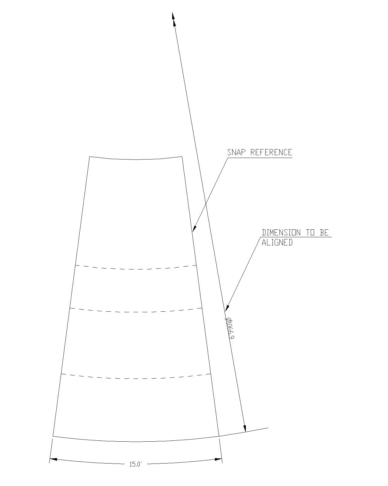
but my issue is that i want these dimension to snap for a certain angle with reference to the edge of the model.
And i want then to automatically align with that angle if i change the revolve angle.....
Please somebody help....I'm really in trouble regarding this......
This thread is inactive and closed by the PTC Community Management Team. If you would like to provide a reply and re-open this thread, please notify the moderator and reference the thread. You may also use "Start a topic" button to ask a new question. Please be sure to include what version of the PTC product you are using so another community member knowledgeable about your version may be able to assist.
- Labels:
-
2D Drawing
- Mark as New
- Bookmark
- Subscribe
- Mute
- Subscribe to RSS Feed
- Permalink
- Notify Moderator
I think an image for clarification is in order here.
- Mark as New
- Bookmark
- Subscribe
- Mute
- Subscribe to RSS Feed
- Permalink
- Notify Moderator

here's the image....
The diametrical dimension needs to be snap at a certain angle or any from the parts edge.....need help here
- Mark as New
- Bookmark
- Subscribe
- Mute
- Subscribe to RSS Feed
- Permalink
- Notify Moderator
I wish a lot of features in detailing were more intuitive.
Typically, this dimension would be specified as a Z-Radius so you can show a centerline mark.
Even that has a bug in that it doesn't draw the tail correctly and draws an arc on the opposite side.
If you have active maintenance, feel free to create an idea for consideration.
edit: I reported the Z-Radius issues... below is Creo 3 ... Creo 2 also adds an extension line to the opposite side of the part.
- Mark as New
- Bookmark
- Subscribe
- Mute
- Subscribe to RSS Feed
- Permalink
- Notify Moderator
Thanks for your reply...i think i can accommodate that...


