
Turn on suggestions
Auto-suggest helps you quickly narrow down your search results by suggesting possible matches as you type.
Showing results for
Please log in to access translation
Turn on suggestions
Auto-suggest helps you quickly narrow down your search results by suggesting possible matches as you type.
Showing results for
Community Tip - New to the community? Learn how to post a question and get help from PTC and industry experts! X
- Community
- Creo+ and Creo Parametric
- 3D Part & Assembly Design
- Curved edges exported to dxf from Creo drawing
Translate the entire conversation x
Please log in to access translation
Options
- Subscribe to RSS Feed
- Mark Topic as New
- Mark Topic as Read
- Float this Topic for Current User
- Bookmark
- Subscribe
- Mute
- Printer Friendly Page
Curved edges exported to dxf from Creo drawing
Jun 05, 2014
08:03 AM
- Mark as New
- Bookmark
- Subscribe
- Mute
- Subscribe to RSS Feed
- Permalink
- Notify Moderator
Please log in to access translation
Jun 05, 2014
08:03 AM
Curved edges exported to dxf from Creo drawing
All
One of our users is having an issue with exporting dxfs from Creo drawings...specifically with curved edges (like rounds) appearing as jagged straight lines. On the model the jagged edges are visible but this is rectified by changing the relative accuracy from 0.0012 to 0.0001 (Is this increasing or decreasing the accuracy?) so I appreciate it is a size thing in terms of the model.
So he fully regenerates the model and drawing and then exports the dxf again....when he opens the dxf in AutoCAD it has the jagged edges. If he opens it in another product called DraftSight the edges are smooth. That in itself is odd.
The problem we have is that he sends the dxf to Sigmanest (without opening it in either AutoCAD or Draftsight) for nesting on a piece of sheetmetal. When the part is physically cut it has jagged edges not smooth.
I'm at a loss as to know which program is causing the problem...he is the only one out of 35 users with this issue.
Anybody got any ideas?
Regards,
Neal
This thread is inactive and closed by the PTC Community Management Team. If you would like to provide a reply and re-open this thread, please notify the moderator and reference the thread. You may also use "Start a topic" button to ask a new question. Please be sure to include what version of the PTC product you are using so another community member knowledgeable about your version may be able to assist.
Labels:
- Labels:
-
Sheet Metal Design
4 REPLIES 4
Jun 05, 2014
08:19 AM
- Mark as New
- Bookmark
- Subscribe
- Mute
- Subscribe to RSS Feed
- Permalink
- Notify Moderator
Please log in to access translation
Jun 05, 2014
08:19 AM
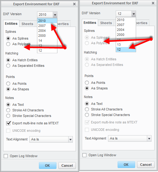
Try playing with the version of DXF. There are some differences with splines and polylines that could come into play.
[cid:image001.png@01CF8096.D1C5BAC0]
Ron
[cid:image001.png@01CF8096.D1C5BAC0]
Ron
Jun 05, 2014
09:23 AM
- Mark as New
- Bookmark
- Subscribe
- Mute
- Subscribe to RSS Feed
- Permalink
- Notify Moderator
Please log in to access translation
Jun 05, 2014
09:23 AM
Try making a part that is as simple as possible - like a square with a single radius that exhibits the difference and export that to DXF from a 'good' computer and the 'bad' computer.
Then open each one with a text editor to see if there is a difference in the header (will tell what version) or in the geometry.
With luck the geometry is identical and it's the version that's a problem. If both are different there are other settings to deal with.
Autodesk hosts DXF format information http://www.autodesk.com/techpubs/autocad/acad2000/dxf/entities_section.htmto help understand what the file contents means. It's not difficult, just tedious. Hence the suggestion for a really simple part.
x
Jun 05, 2014
10:11 AM
- Mark as New
- Bookmark
- Subscribe
- Mute
- Subscribe to RSS Feed
- Permalink
- Notify Moderator
Please log in to access translation
Jun 05, 2014
10:11 AM
David we have an automatic process for creating DXF off a pro/e model .
Suggest you have a play around with these pro/e settings
dxf_out_comments no
dxf_out_drawing_scale yes
dxf_out_scale_views yes
dxf_out_sep_dim_w_breaks no
dxf_out_stroke_text no
intf2D_out_enhanced_ents none
intf_out_layer none
intf2D_out_acad_mtext yes
intf2D_out_acad_text_align as_is
intf2D_out_pnt_ent yes
intf2D_out_open_log_window no
dxf_export_format 14
save_hidden_items_w_status no
Randall
Jun 05, 2014
10:23 AM
- Mark as New
- Bookmark
- Subscribe
- Mute
- Subscribe to RSS Feed
- Permalink
- Notify Moderator
Please log in to access translation
Jun 05, 2014
10:23 AM
From what I remember, the biggest change to output curves verses 'polylines' is with the option: dxf_export_format 14
I think V14 was the first version of Autocad to convert polylines to curves or arcs through three points along the curve in a drawing or DXF. Exporting as V12 (I think this is the default in CREO) should always output as polylines.
Christopher F. Gosnell
FPD Company
124 Hidden Valley Road
McMurray, PA 15317


