
Turn on suggestions
Auto-suggest helps you quickly narrow down your search results by suggesting possible matches as you type.
Showing results for
Please log in to access translation
Turn on suggestions
Auto-suggest helps you quickly narrow down your search results by suggesting possible matches as you type.
Showing results for
Community Tip - If community subscription notifications are filling up your inbox you can set up a daily digest and get all your notifications in a single email. X
- Community
- Creo+ and Creo Parametric
- 3D Part & Assembly Design
- Custom hole table to auto-output custom data...
Translate the entire conversation x
Please log in to access translation
Options
- Subscribe to RSS Feed
- Mark Topic as New
- Mark Topic as Read
- Float this Topic for Current User
- Bookmark
- Subscribe
- Mute
- Printer Friendly Page
Custom hole table to auto-output custom data...
Feb 23, 2018
03:14 PM
- Mark as New
- Bookmark
- Subscribe
- Mute
- Subscribe to RSS Feed
- Permalink
- Notify Moderator
Please log in to access translation
Feb 23, 2018
03:14 PM
Custom hole table to auto-output custom data...
Hello Community,
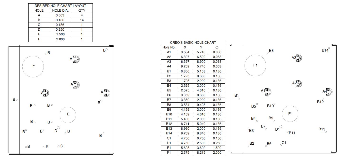
I am trying to configure Creo to output a hole table to show a Hole label, Hole Diameter, & Qty. of each hole with the holes being grouped into single hole letter identifiers. Likewise i would like Creo to populate the drawing view with the labels accordingly. Is there any way to accomplish this?
The image I have attached shows what I am trying to achieve. Right view is Creo's original output when using the Hole Table command, the left view is what I am trying to achieve when using the Hole Table command.
Thank you for any help on this.
Labels:
- Labels:
-
2D Drawing
6 REPLIES 6
Feb 23, 2018
03:21 PM
- Mark as New
- Bookmark
- Subscribe
- Mute
- Subscribe to RSS Feed
- Permalink
- Notify Moderator
Please log in to access translation
Feb 23, 2018
03:21 PM
Looks like a very useful enhancement.
I am not sure PTC even thought to take it to this next level.
Certainly worth an Idea submission.
Feb 23, 2018
03:27 PM
- Mark as New
- Bookmark
- Subscribe
- Mute
- Subscribe to RSS Feed
- Permalink
- Notify Moderator
Please log in to access translation
Feb 23, 2018
03:27 PM
Not an option as of now. I will echo with Tom for an Idea.
Feb 23, 2018
03:29 PM
- Mark as New
- Bookmark
- Subscribe
- Mute
- Subscribe to RSS Feed
- Permalink
- Notify Moderator
Please log in to access translation
Feb 23, 2018
03:29 PM
I think you could use both charts.
PTC's default one lists the locations but no hole size.
Your chart lists the hole size and a summary of the number of each hole but no location.
Leave the original hole location chart alone and add a new hole summary chart, which is what you have. Make them both optional so each company can choose to use either one or both.
An added enhancement to the current PTC chart would be hole diameter. I don't use hole charts so maybe that is already in there just not used in your configuration.
Feb 23, 2018
03:56 PM
- Mark as New
- Bookmark
- Subscribe
- Mute
- Subscribe to RSS Feed
- Permalink
- Notify Moderator
Please log in to access translation
Feb 23, 2018
03:56 PM
The chart and model view on the left is made up of blank table cells which I filled in manually as well as the labels on the view itself, they are just single line notes. The view on the right is what Creo generates when you use the Hole Table command and it updates the table and the labels on the drawing view dynamically whenever you make a change to the model.
The hole table on the right is the table we use for our sheet metal flat views.
What I am trying to do is tell Creo to take the left example and treat it like the right example so that it updates dynamically when the model is changed.
The hole diameter is already a parameter that can be added or removed from the hole table.
Feb 23, 2018
07:28 PM
- Mark as New
- Bookmark
- Subscribe
- Mute
- Subscribe to RSS Feed
- Permalink
- Notify Moderator
Please log in to access translation
Feb 23, 2018
07:28 PM
Have you looked at creating your own repeat region table?
Some help with the search function to gather the target holes should make this work similar to a BOM.
Feb 23, 2018
08:16 PM
- Mark as New
- Bookmark
- Subscribe
- Mute
- Subscribe to RSS Feed
- Permalink
- Notify Moderator
Please log in to access translation
Feb 23, 2018
08:16 PM
Doing what you want is pretty much what is described in ASME Y14.5-2009, Figure 1-51. I'm sure PTC has a copy somewhere. For a hole chart you need at least the coordinates. Splitting out the letter vs size and quantity makes the result much more legible, but they aren't useful if there is only one there.


