Community Tip - Learn all about PTC Community Badges. Engage with PTC and see how many you can earn! X
- Community
- Creo+ and Creo Parametric
- 3D Part & Assembly Design
- Designing in Creo
- Subscribe to RSS Feed
- Mark Topic as New
- Mark Topic as Read
- Float this Topic for Current User
- Bookmark
- Subscribe
- Mute
- Printer Friendly Page
Designing in Creo
- Mark as New
- Bookmark
- Subscribe
- Mute
- Subscribe to RSS Feed
- Permalink
- Notify Moderator
Designing in Creo
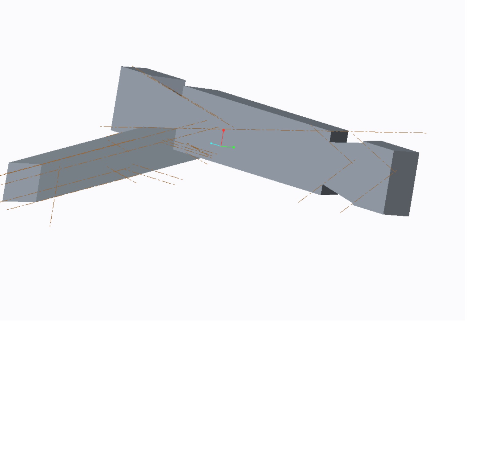
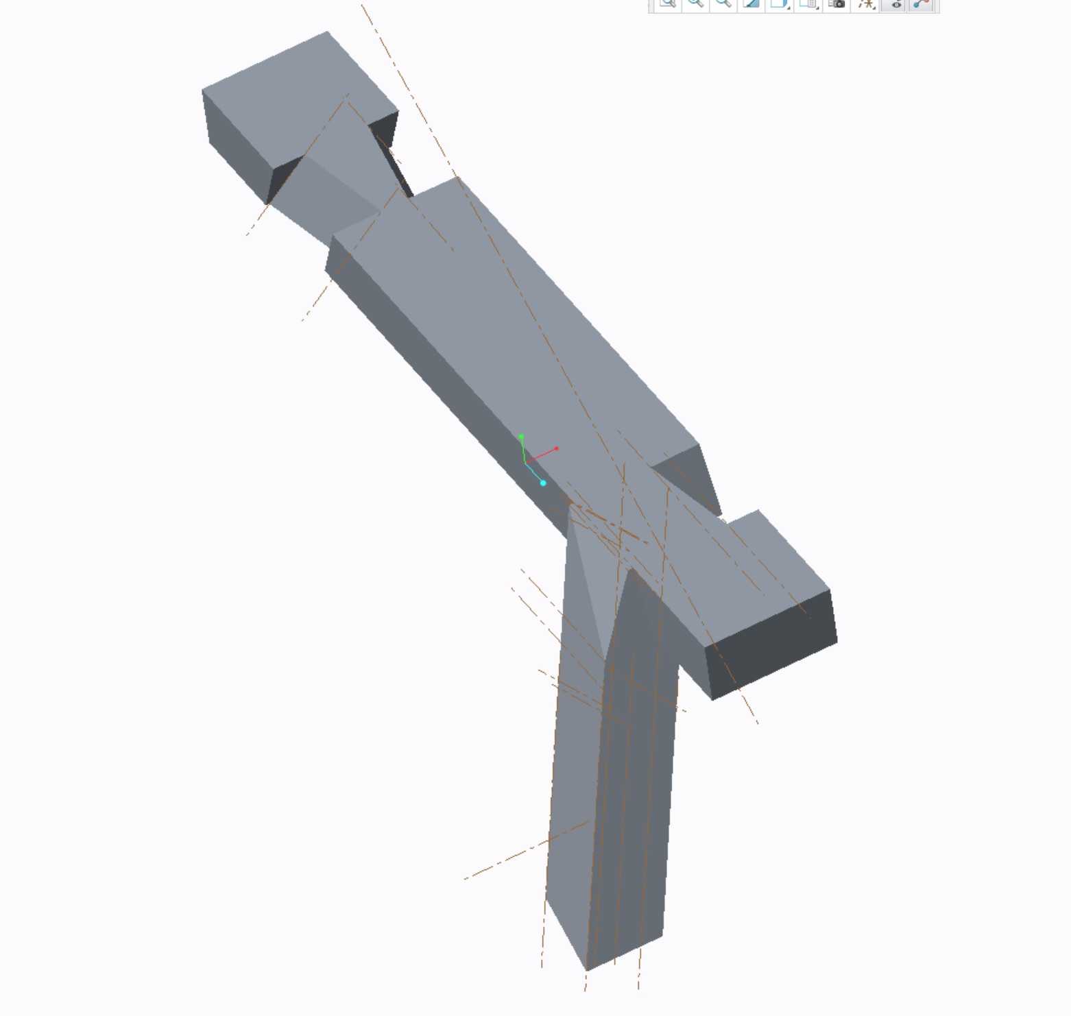
I've started to design a simple saw bench. A cross beam with 4 legs, which Carpenters use, and develop the complex geometry using planes as a teaching aid. Most of the teaching aids I've seen are a complete design bringing components together to be assembled. Here I've design the assembly to match the area and support required but now I'm now stuck as I cannot seem to copy the "leg" to develop the assembly and drawings as would normally be the case.
How should I go about this? I began by creating the "cut-outs" and to prove the design filled the cut-out with a short leg as shown. It would appear that I cannot easily separate these now to "reverse engineer" the design. Are the any examples of copying and separating geometry like this?


Solved! Go to Solution.
- Labels:
-
Surfacing
Accepted Solutions
- Mark as New
- Bookmark
- Subscribe
- Mute
- Subscribe to RSS Feed
- Permalink
- Notify Moderator
Anything solid that touches each other in a Creo part file will merge.
Each part would be made and then assembles in an assembly.
Once the assembly is created, you can create associations between parts (use this capability with caution)
You also have the option to create assembly cuts by assembling raw materials (just a board).
Each of these options have caveats. For teachable situations, maybe all should be covered.
- Mark as New
- Bookmark
- Subscribe
- Mute
- Subscribe to RSS Feed
- Permalink
- Notify Moderator
If I'm understanding correctly, you will need to model 2 parts and assemble them. My image below is of angle iron that is cut out to fit another piece of angle iron. The parts are separate parts assembled. In my case, they are welded together. Yours would be nailed or screwed together, but same concept applies. Each part represents a physical part in the real world.

- Mark as New
- Bookmark
- Subscribe
- Mute
- Subscribe to RSS Feed
- Permalink
- Notify Moderator
Anything solid that touches each other in a Creo part file will merge.
Each part would be made and then assembles in an assembly.
Once the assembly is created, you can create associations between parts (use this capability with caution)
You also have the option to create assembly cuts by assembling raw materials (just a board).
Each of these options have caveats. For teachable situations, maybe all should be covered.
- Mark as New
- Bookmark
- Subscribe
- Mute
- Subscribe to RSS Feed
- Permalink
- Notify Moderator
Thanks all.
I've used the model to create parts from scratch then assemble them together. That does seem at odds with how I use to design on the drawing board but something I will need to get use to as I learn the product. Are there any books or reference material that would help me get up to speed quicker? I have the basic and advanced creo3 books from SDC but they follow a "proven" design. I'm looking for the initial design intent to drawings.
- Mark as New
- Bookmark
- Subscribe
- Mute
- Subscribe to RSS Feed
- Permalink
- Notify Moderator
There were some complementary PTC University courses included in my re-upping my long expired license.
I found it a fairly nice pace and certainly complete.
As to the "how to" convert from a design layout on layers of Mylar to CAD, the conversion is similar from a practical standpoint.
In early wireframe systems, I started working with layers exclusively for part segregation (and easily managed). This was for the most part the colors on the Mylar on the associative layer. CAD grew up since then with solid modelers. Now we bury little 2D sketches all over the place in order to see the 3D we've been striving to visualize for centuries. And the beauty of this is that there is no "right" way for everyone. The best we can do is match our efforts to a business model. The drafting board of today is really no different when it comes to organizing your thoughts. I rarely start a design challenge in the computer.
- Mark as New
- Bookmark
- Subscribe
- Mute
- Subscribe to RSS Feed
- Permalink
- Notify Moderator
You really need to explore and learn how to use Top Down Design within Creo. This technique is much more akin to the old school drawing board design that you refer to. It may seem daunting, cumbersome and/or complex at first, but we couldn't live without it.
- Mark as New
- Bookmark
- Subscribe
- Mute
- Subscribe to RSS Feed
- Permalink
- Notify Moderator
Agreed. You want to look at the use of Skeletons & Copy Geom. Be very aware of the caveats with external references and part re-use.
- Mark as New
- Bookmark
- Subscribe
- Mute
- Subscribe to RSS Feed
- Permalink
- Notify Moderator
Hi Tom,
All good stuff (as always from Ton).
There is a way to "cheat" in just the part. You make that leg that you were looking at as a surface (e.g. a surface extrude rather than a solid extrude. You can cap these surfaces so it looks like a solid but isn't. It forms a quilt that can be coloured to distinguish it from the solid. And this has the virtue of not automatically merging with the solid though you can solidify it/them later.
This is a powerful technique for visualisation however many people shy away for surfaces. It can and should be be used in the mentioned Top Down Design method (Lar) with a Skeleton Part and Publish and Copy Geom features (Dan).
Generally most people start with the single parts and make an assembly. In this case you do your complex stuff in the base and the legs are pretty simple with just compound angle cuts.
Probably sounds like gobbledygook but just to give you the idea that there are many ways to achieve things.
Regards, Brent.


