Community Tip - You can change your system assigned username to something more personal in your community settings. X
- Community
- Creo+ and Creo Parametric
- 3D Part & Assembly Design
- Did You Know? PTC Creo 3.0 Enhancements: Geometric...
- Subscribe to RSS Feed
- Mark Topic as New
- Mark Topic as Read
- Float this Topic for Current User
- Bookmark
- Subscribe
- Mute
- Printer Friendly Page
Did You Know? PTC Creo 3.0 Enhancements: Geometric Tolerances
- Mark as New
- Bookmark
- Subscribe
- Mute
- Subscribe to RSS Feed
- Permalink
- Notify Moderator
Did You Know? PTC Creo 3.0 Enhancements: Geometric Tolerances
Geometric tolerances in PTC Creo 3.0 have been enhanced to provide better support for ASME and ISO drawing standards. From additional symbols to text justification, PTC Creo enables you to customize your geometric tolerances to provide clear, accurate drawings. In this post, Raphael Nascimento, a PTC Product Manager, explains how to use the new functionality:
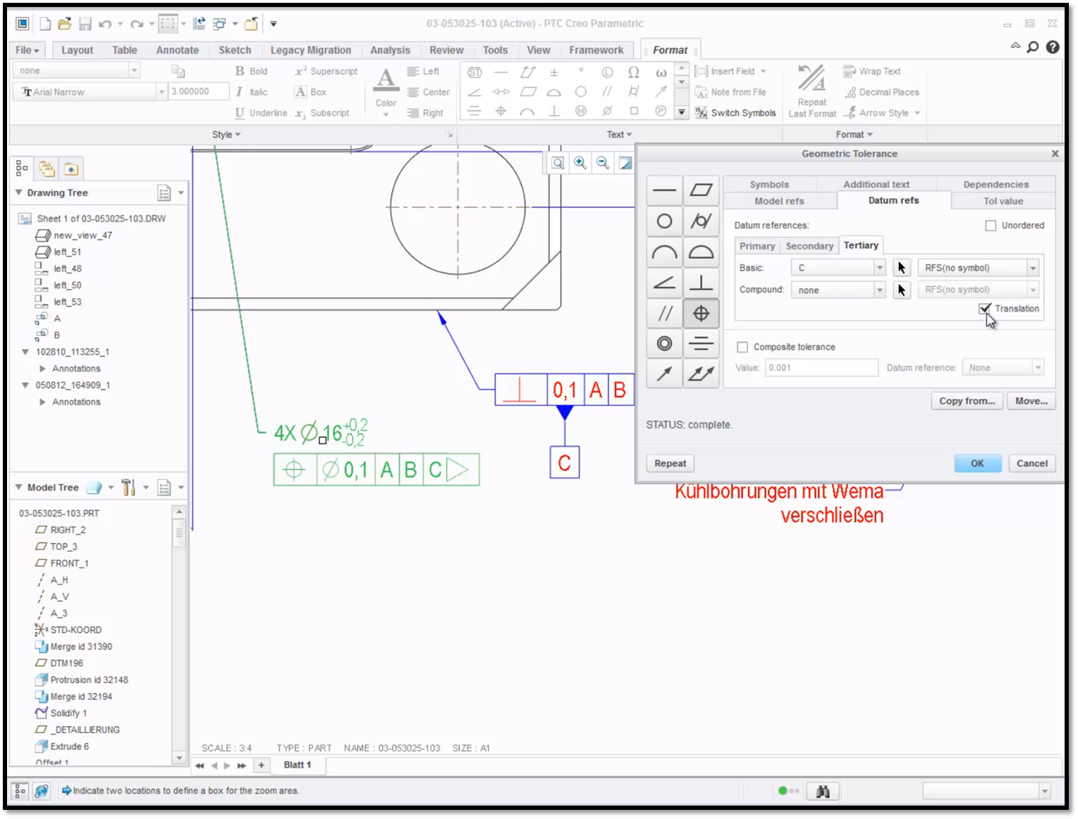
If you follow the ASME standard, you can now add the translation modifier to any of the datum references. To do so, right click on the geometric tolerance and select Properties. Using the Geometric Tolerance dialogue box, navigate to the Datum refs tab and mark the Translation checkbox. Use the tabs under Datum References to select the Translation checkbox for each of the datum references. Once you have finished, click OK to accept the changes.

The translation checkbox has been marked for the tertiary reference of the geometric tolerance in green.
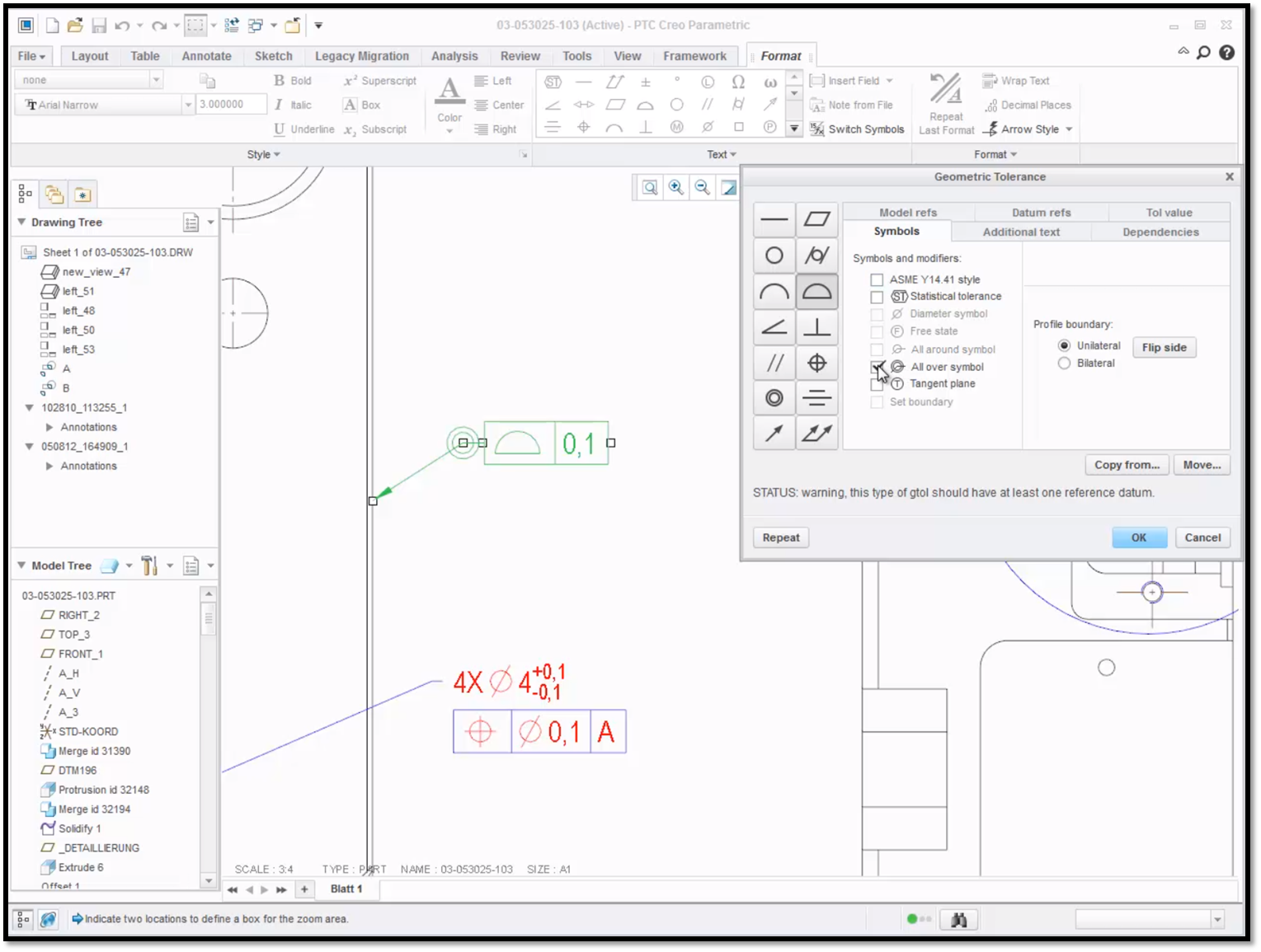
Another enhancement for the ASME standard is the ability to add the all over symbol to the leader elbow of the geometric tolerance. This option is found in the Symbols tab of the Geometric Tolerance dialogue box. Right click on the geometric tolerance and select Properties to open the Geometric Tolerance dialogue box. Navigate to the Symbols tab and mark the checkbox for All over symbol. The All over symbol will appear next to the geometric tolerance. Click OK to accept your changes.

Notice that All over symbol has appeared to the left of the leader elbow in green.
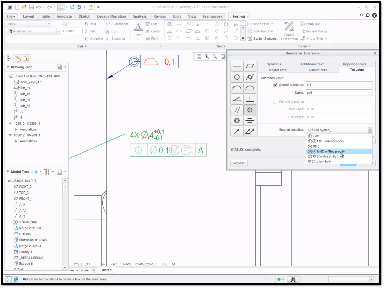
If you follow the ISO standard, you can now include the reciprocity symbol into the tolerance value compartment along with either the maximum material condition or least material condition modifiers. Right click on the geometric tolerance and click Properties to open the Geometric Tolerance dialogue box. Navigate to the tolerance value (Tol value) tab and open the Material Condition drop down menu to see the options. In this example, we selected MMC w/Reciprocity. Click OK to accept the changes.

Here you can see that changes are now visible in green.
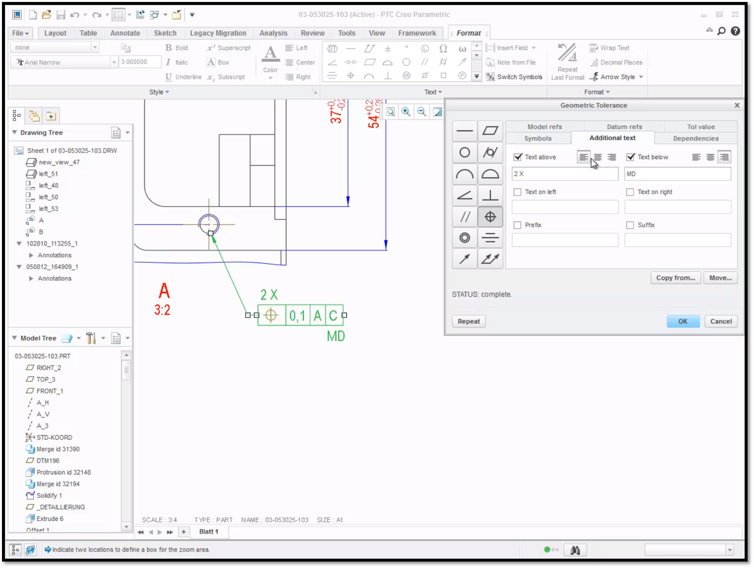
We’ve also enhanced the functionality for specifying additional text around the geometric tolerance symbol. You now have option to add text above, below, to the right, or to the left of the geometric tolerance symbol. Right click on the geometric tolerance and click Properties to open the Geometric Tolerance dialogue box. Navigate to the Additional text tab and enter the text that you want to appear. Next, justify the text to the right, left, or center, depending on whether you follow ISO or ASME standards. Click OK to accept your changes.

Notice that 2X was added to the top left of the geometric tolerance and MD was added to the bottom right.
To learn more about geometric tolerances check out our video tutorial (“Reviewing Geometric Tolerance”).
Stay tuned to our “Did You Know” blog series as we cover all of the exciting, new enhancements in PTC Creo 3.0.
For more in-depth product feature explanations, visit our Tech Tips area.
Have some ideas about what PTC Creo product features you’d like to learn more about? Send me a message or leave a comment below and we’ll write up the best ideas from the community. Thanks for reading, looking forward to all of your feedback!
In case you missed it, see what’s new and check out our recent Did You Know posts covering PTC Creo 3.0 enhancements:
- Fast Facts! Quick Tips for Using PTC Creo - Drawings Part 1
- Did You Know? PTC Creo 3.0 Enhancements: Draft Analysis
- Did You Know? Connection Analysis
This thread is inactive and closed by the PTC Community Management Team. If you would like to provide a reply and re-open this thread, please notify the moderator and reference the thread. You may also use "Start a topic" button to ask a new question. Please be sure to include what version of the PTC product you are using so another community member knowledgeable about your version may be able to assist.
- Labels:
-
General


