- Community
- Creo+ and Creo Parametric
- 3D Part & Assembly Design
- Re: Draft modeling on non-plane surface
- Subscribe to RSS Feed
- Mark Topic as New
- Mark Topic as Read
- Float this Topic for Current User
- Bookmark
- Subscribe
- Mute
- Printer Friendly Page
Draft modeling on non-plane surface
- Mark as New
- Bookmark
- Subscribe
- Mute
- Subscribe to RSS Feed
- Permalink
- Notify Moderator
Draft modeling on non-plane surface
Hi everybody,
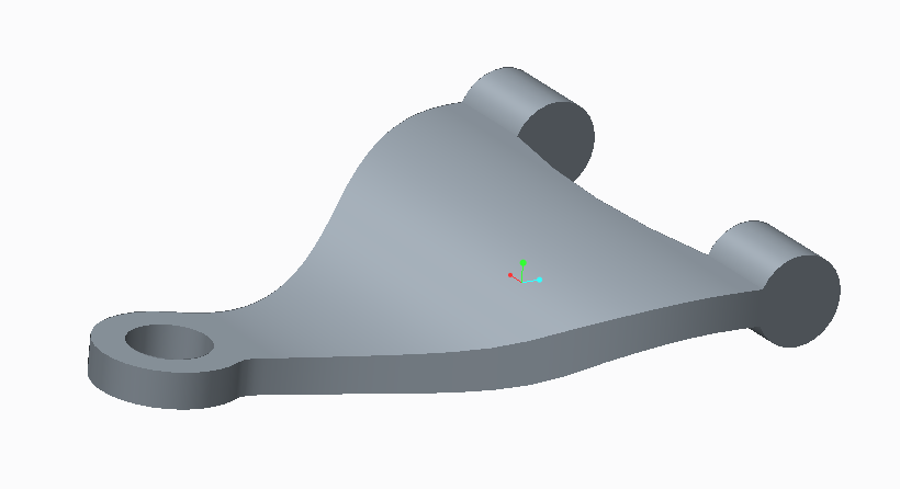
At this moment, I have a casting project at University in which i have to design a cast part on Creo 2.0. The teacher gives us a badly design part for casting, and we have to improve the deisgn of it. The part is the following :

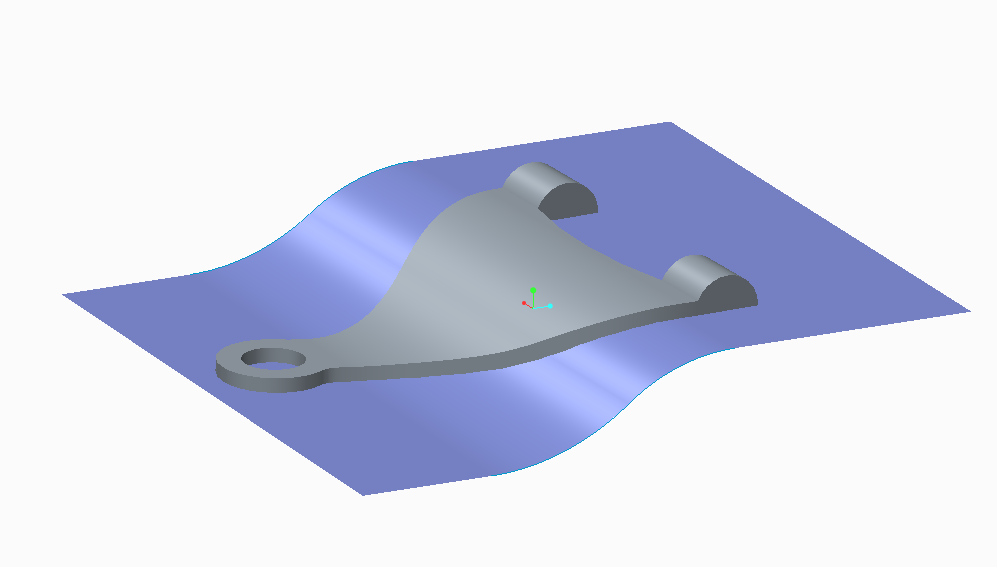
The first step for me is to make drafts on the side of the part, and the parting line is the following blue surface :

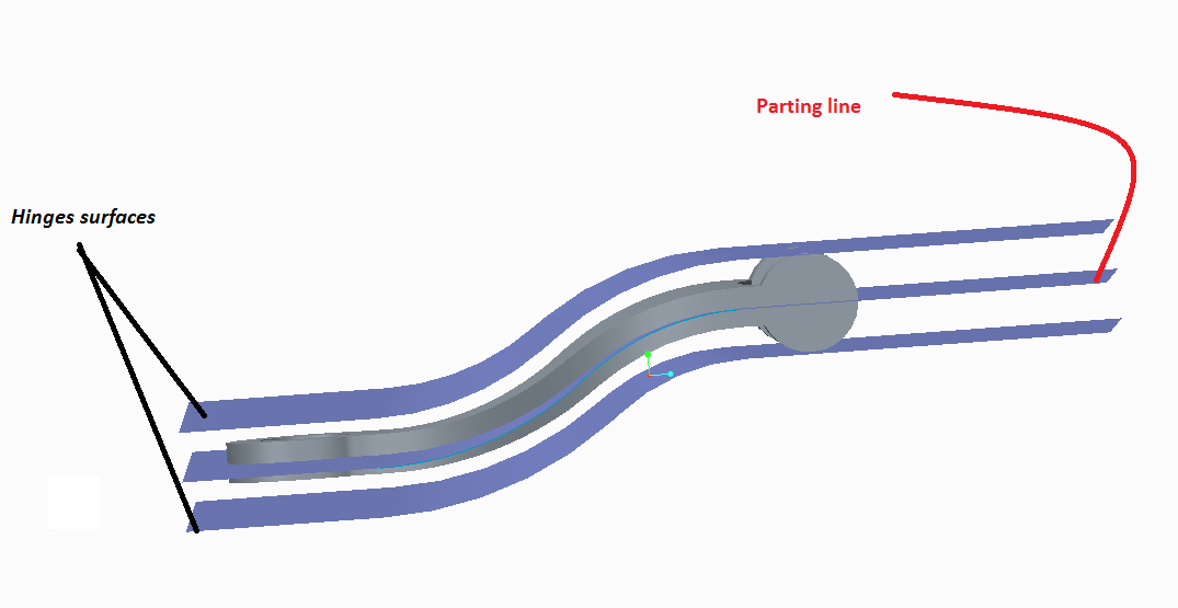
After that, i have big problems to create my draft. I want to create 2 drafts of 3 degrees on each side of the parting line. To make this, i have created two offset surfaces, in order to use these 2 surfaces as hinges surfaces :

However, it doesn't work and creo doesn't allow me to make draft with these 2 surfaces as hinges.
Does someone know why and can help me?
Thanks a lot!
Best regards
This thread is inactive and closed by the PTC Community Management Team. If you would like to provide a reply and re-open this thread, please notify the moderator and reference the thread. You may also use "Start a topic" button to ask a new question. Please be sure to include what version of the PTC product you are using so another community member knowledgeable about your version may be able to assist.
- Labels:
-
Data Exchange
- Mark as New
- Bookmark
- Subscribe
- Mute
- Subscribe to RSS Feed
- Permalink
- Notify Moderator
I hake skills in design of forged parts. You need something similar to this pdf?
- Mark as New
- Bookmark
- Subscribe
- Mute
- Subscribe to RSS Feed
- Permalink
- Notify Moderator
Hello,
Thanks for your answer. Sorry for my late answer, i've just come back from holidays!
It is exactly the same think i have to do, but as i explained, i have difficulties to design my draft with draft tool on creo. What do you think about the metohd i explained in my introduction? Something goes wrong but i don't know why...
- Mark as New
- Bookmark
- Subscribe
- Mute
- Subscribe to RSS Feed
- Permalink
- Notify Moderator
The draft feature in Creo is excellent.
You would use the outer wall intent edge as the surfaces to draft.
Use the parting surface in the middle as your hinge.
Use the split draft option.
- Mark as New
- Bookmark
- Subscribe
- Mute
- Subscribe to RSS Feed
- Permalink
- Notify Moderator
Hello,
Thanks for your answer. Sorry for my late answer, i've just come back from holidays!
Actually i use the outer wall as the surfaces to draft, the two offset surfaces as hinges, i choose the option "split by object", then i choose my parting line as object... is it wrong?
- Mark as New
- Bookmark
- Subscribe
- Mute
- Subscribe to RSS Feed
- Permalink
- Notify Moderator
Maxime,
The way that I described using the parting surface as a hinge would give a result with the parting profile staying the same and the wall would draft inside from the widest point.
I'm not sure what results you would get using outer surfaces as a hinge.
- Mark as New
- Bookmark
- Subscribe
- Mute
- Subscribe to RSS Feed
- Permalink
- Notify Moderator
Paul,
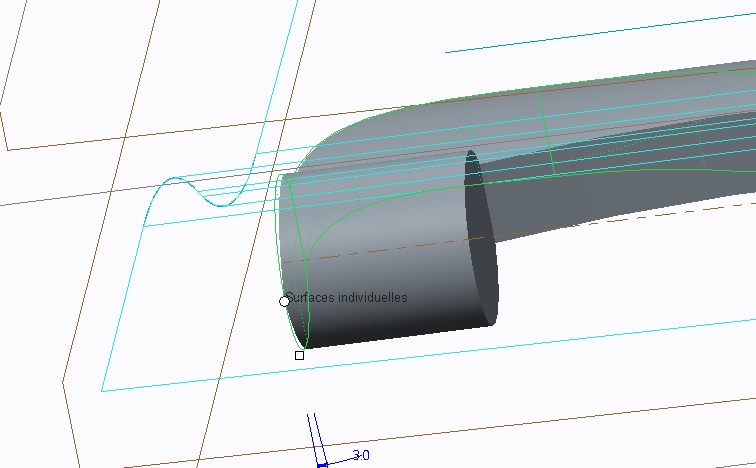
Indeed i have tried your solution and it seems to work. However, it removes material, as we can see on the following picture :

How can i do? i can calculate the amount of material i have to add but it is not a proper way to make this feature, and this amount of material depends of the draft angle...
Thanks ![]()
- Mark as New
- Bookmark
- Subscribe
- Mute
- Subscribe to RSS Feed
- Permalink
- Notify Moderator
Actually it is ok, i have managed my part to make it corretly. Thanks a lot for your help. Last question : to create my core/patern, i 'd like to convert an assembly to part. It is possible with catia, is it possible with creo? Thx ![]() !
!
- Mark as New
- Bookmark
- Subscribe
- Mute
- Subscribe to RSS Feed
- Permalink
- Notify Moderator
I'm glad that this was the draft type you needed as the other way is a little more tricky to do.
I know I'm not much help but I do know that part models can be made from an assembly because I've seen it done. Unfortunately I'm not sure how to do it.
I have been using the Pro-Mold extension to do the cavities for my dies. With this you have to 1st make die volumes and then you can make the separate parts by using the Cavity Insert tool.
I would like to know this myself from assembly.
- Mark as New
- Bookmark
- Subscribe
- Mute
- Subscribe to RSS Feed
- Permalink
- Notify Moderator
Maxime
I believe you can save the assembly as an IGES file open the iges as a part file.
- Mark as New
- Bookmark
- Subscribe
- Mute
- Subscribe to RSS Feed
- Permalink
- Notify Moderator
There are a lot of ways to make this work. If I must use the hinge lines you picked, I would project the edges to those surfaces. Then sweep a surface with the 3 degree taper in both directions... maybe a VSS if I have to account for separation variation. The key element would be to orient the section normal to the pull direction. Having these surfaces available, you now have "extrude up to" surfaces. A lot of options to add the material to a solid body at this point.


