Community Tip - If community subscription notifications are filling up your inbox you can set up a daily digest and get all your notifications in a single email. X
- Community
- Creo+ and Creo Parametric
- 3D Part & Assembly Design
- Re: Drafting and order of features.
- Subscribe to RSS Feed
- Mark Topic as New
- Mark Topic as Read
- Float this Topic for Current User
- Bookmark
- Subscribe
- Mute
- Printer Friendly Page
Drafting and order of features.
- Mark as New
- Bookmark
- Subscribe
- Mute
- Subscribe to RSS Feed
- Permalink
- Notify Moderator
Drafting and order of features.
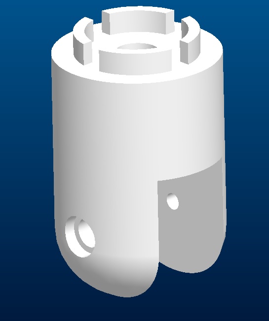
I am familiar with parting lines and pull directions for molded or cast parts, but I have not had a lot of experience designing parts with draft. I have an initial concept of a part shown in the pictures. My two thoughts for the parting line would be either the top of the cylinder near the four tabs or where the slot at the bottom of the part intersects the cylinder. There is some geometry in the bottom of the slot shown in the second picture.
Besides the parting line question, I am also wondering about the order of operation. Typically rounds/radii go towards the end of the part. What about draft? Do you get a concept done similar to what I have and then add draft, or is it added up stream. This is a fairly simple part, so if it needs to be upstream, I can easily recreate the part if needed.
Thanks for suggestions and ideas,
Dale


This thread is inactive and closed by the PTC Community Management Team. If you would like to provide a reply and re-open this thread, please notify the moderator and reference the thread. You may also use "Start a topic" button to ask a new question. Please be sure to include what version of the PTC product you are using so another community member knowledgeable about your version may be able to assist.
- Labels:
-
General
- Mark as New
- Bookmark
- Subscribe
- Mute
- Subscribe to RSS Feed
- Permalink
- Notify Moderator
This is a common question for many working with molded parts.
The simple one to answer is the drafts and chamfers. Add them after drafts. All too often a feature will fail from an arbitrary round before draft.
As to parting line, this is usually driven by the design intent. With some license... I would consider the flat face on the 1st image to be the logical parting line providing flash at the assumed mating interface, in this case. Also remember to logically direction of pull for the center bore which I would probably keep with the countersink feature.
Only a few design intents would change my perspective. If the cylinder and 4 tabs were a critical mating feature, and a fillet or chamfer on that edge was desired or even critical. I would be aware that flash at the transition would be clearly visible, or would require post mold operation.
As to when to apply the draft; rarely do people think draft while modeling and they spend a lot of time after the fact to apply it. I don't know if the "dome" is sculpted or a simple round, but features like this can really slow you down when adding draft. I will do both but I like to work on primary features with draft already defined. Some things just don't lend themselves to doing this simply so those I might feature straight, consider the tooling, and add drafts at that point (before I am too committed with more dependent feature).
- Mark as New
- Bookmark
- Subscribe
- Mute
- Subscribe to RSS Feed
- Permalink
- Notify Moderator
The main cylinder with the dome was a revolve. I went back and added angle to the outer edge of the revolve to get "draft" for the cylinder.
The center pocket so far I was able to use the draft tool. (Actually I tried this after not getting the outside to draft - when it worked, I realized that the draft function probably did not like the transition from the cylinder to the dome.)
Any other input would appreciated.
Thanks, Dale
- Mark as New
- Bookmark
- Subscribe
- Mute
- Subscribe to RSS Feed
- Permalink
- Notify Moderator
I had rounds/fillets on the part when doing the intial concept, but blew them away on a copy when starting to add draft.
- Mark as New
- Bookmark
- Subscribe
- Mute
- Subscribe to RSS Feed
- Permalink
- Notify Moderator
I might even extrude the slot with draft in the sketch and revolve the step next to the countersink after the cut also including the draft on the ID.
I would also to the slide feature with a revolve including the draft, rather than a simply hole.
the 4 tabs I would simply extrude with taper. I suppose the slot could be done this way too.
I take it you found the config.pro option: minimum_angle_dimension ![]()
- Mark as New
- Bookmark
- Subscribe
- Mute
- Subscribe to RSS Feed
- Permalink
- Notify Moderator
The tabs are anti rotation features that interact with the mating part. Another quick question from material savers standpoint. I have some leeway with them. I could make them smaller in diameter or larger. My thought is that I would put them closer to the through bolt hole and then place material saver between them and the outside serface. Any comments?
- Mark as New
- Bookmark
- Subscribe
- Mute
- Subscribe to RSS Feed
- Permalink
- Notify Moderator
I am usually less concerned with material savers than I am with shrinkage. A constant wall thickness and 60% ribs is always a good objective.
I would not make the alignment features smaller in diameter. Larger means better location. In the center of this, you might be able to get away with some coring in the form of a recess, preferably by leaving the wall for the screw depending on the interface.
- Mark as New
- Bookmark
- Subscribe
- Mute
- Subscribe to RSS Feed
- Permalink
- Notify Moderator
- Mark as New
- Bookmark
- Subscribe
- Mute
- Subscribe to RSS Feed
- Permalink
- Notify Moderator
I have it, but have not coverted over yet.
I do most of my work in WF5/Creo.
I'll take a lock at is shortly on another machine (so I don't get them confused).
- Mark as New
- Bookmark
- Subscribe
- Mute
- Subscribe to RSS Feed
- Permalink
- Notify Moderator
Just curious why you add the step back into the slot versus remove the material? Any adherent benefits of adding material versus taking away?
- Mark as New
- Bookmark
- Subscribe
- Mute
- Subscribe to RSS Feed
- Permalink
- Notify Moderator
Dale Rosema wrote:
Just curious why you add the step back into the slot versus remove the material? Any adherent benefits of adding material versus taking away?
Absolutely... I am not bound by tooling and machining processes. In this case, I am simplifying the wall feature (slot) cut. When I can create a draft face with a single cut, rather than a "merging" features, I will.
- Mark as New
- Bookmark
- Subscribe
- Mute
- Subscribe to RSS Feed
- Permalink
- Notify Moderator
I see now how that simplifies things. Before I saw you post about the material saver, I was extruding into the surface from the top versus doing a revolve. I like the revolved better.
- Mark as New
- Bookmark
- Subscribe
- Mute
- Subscribe to RSS Feed
- Permalink
- Notify Moderator
Here is a simple coring as a material saver: You could even make the wall at the screw define a centering locator and loosen the rotational lock's diametical fit.
Ribs would be optional at this step.
Of course, making this particular core really hosed the Rounds.
- Mark as New
- Bookmark
- Subscribe
- Mute
- Subscribe to RSS Feed
- Permalink
- Notify Moderator
I don't get to play with ribs often. Kind of nice to have a feature just work as expected ![]()
prt0076.prt.4 attached
- Mark as New
- Bookmark
- Subscribe
- Mute
- Subscribe to RSS Feed
- Permalink
- Notify Moderator
With the hole with the countersink in the middle, do you typically use revoles instead of a hole feature?
- Mark as New
- Bookmark
- Subscribe
- Mute
- Subscribe to RSS Feed
- Permalink
- Notify Moderator
Since the hole requires draft anyway, I have no aversion to making it a simple revolve. The same with the slide hole draft. I did form the thread using the hole feature so I could inherit the drill diameter from the tables.
I come from the 2000i world where all holes were essentially a revolve feature.


