Community Tip - You can Bookmark boards, posts or articles that you'd like to access again easily! X
- Community
- Creo+ and Creo Parametric
- 3D Part & Assembly Design
- Re: Drawing displays edge that is behind a solid e...
- Subscribe to RSS Feed
- Mark Topic as New
- Mark Topic as Read
- Float this Topic for Current User
- Bookmark
- Subscribe
- Mute
- Printer Friendly Page
Drawing displays edge that is behind a solid even when "no hidden" is used
- Mark as New
- Bookmark
- Subscribe
- Mute
- Subscribe to RSS Feed
- Permalink
- Notify Moderator
Drawing displays edge that is behind a solid even when "no hidden" is used
Why do these edges display in my drawing view? They are behind another solid, and my display is set to "no hidden".
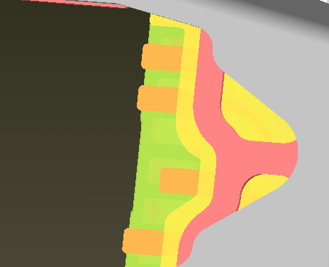
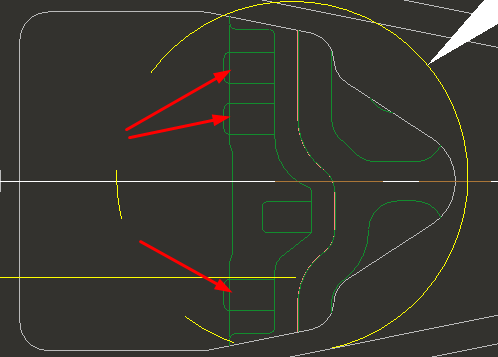
This thread is inactive and closed by the PTC Community Management Team. If you would like to provide a reply and re-open this thread, please notify the moderator and reference the thread. You may also use "Start a topic" button to ask a new question. Please be sure to include what version of the PTC product you are using so another community member knowledgeable about your version may be able to assist.
- Labels:
-
2D Drawing
- Mark as New
- Bookmark
- Subscribe
- Mute
- Subscribe to RSS Feed
- Permalink
- Notify Moderator
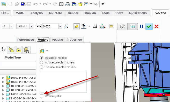
Are they surfaces (quilts)? And is your drawing view a x-section?
- Mark as New
- Bookmark
- Subscribe
- Mute
- Subscribe to RSS Feed
- Permalink
- Notify Moderator
It is a top view of a sheetmetal assembly. I tried the hidden line removal for quilts but that did not work.
I also tried playing around with part accuracies but can't get it to work.
It is an issue because a customer is complaining about it.
- Mark as New
- Bookmark
- Subscribe
- Mute
- Subscribe to RSS Feed
- Permalink
- Notify Moderator
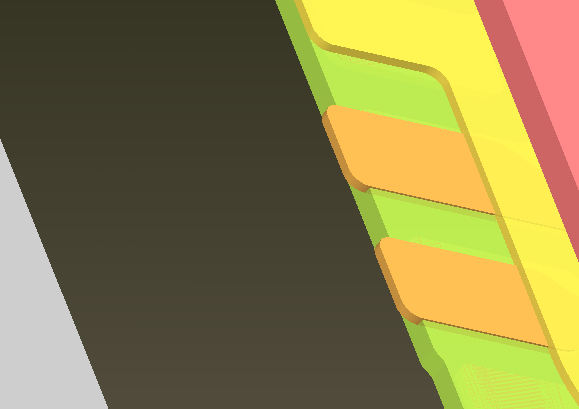
Is there interferences in your assembly? Often interference in assemblies cause hidden line problems.
- Mark as New
- Bookmark
- Subscribe
- Mute
- Subscribe to RSS Feed
- Permalink
- Notify Moderator
There is interference where the lines shows through.
My next solution is to create cuts at these locations, but it will involve resetting several simplified reps, I didn't want to do that.
Thanks for the feedback. I thought maybe there was a display accuracy setting that I could change.
- Mark as New
- Bookmark
- Subscribe
- Mute
- Subscribe to RSS Feed
- Permalink
- Notify Moderator
It doesn't work to create cuts at these locations because there are two bends involved. If the cuts are created in the master rep, the bend locations shift at this rep that I need. I also tried creating the cuts at the rep shown but that does not work because the reference features of the other parts are shifted with other bends. I am activating the part that I need the bends in from the upper assembly so I have reference edges to use. So, still no solution. If ProE displayed correctly at the drawing view I would not have this issue. ![]()
- Mark as New
- Bookmark
- Subscribe
- Mute
- Subscribe to RSS Feed
- Permalink
- Notify Moderator
It's really difficult to follow exactly what the issue is with your feature creation. Can you share the models or if not, a representative model showing your process? Not being able to get a cut in the correct location seems to be odd. And I'm completely lost with the simplified reps.
- Mark as New
- Bookmark
- Subscribe
- Mute
- Subscribe to RSS Feed
- Permalink
- Notify Moderator
I can't share the model because of IP issues. The short answer is the partial depth cut does not follow with the bend, although we have through cuts that do. We have a complex template - the subassembly shown has 7 sheetmetal layers with offset walls and several bends defined with relations (since ProE does not have assembly bends ![]() and thicknesses and radii vary with design). There are about 5 or 6 simp reps that have various bend states and /or part features removed. This is the first time I have run into this particular issue.
and thicknesses and radii vary with design). There are about 5 or 6 simp reps that have various bend states and /or part features removed. This is the first time I have run into this particular issue.
- Mark as New
- Bookmark
- Subscribe
- Mute
- Subscribe to RSS Feed
- Permalink
- Notify Moderator
If it's not a x-section but try hidden line removal for Quilts in the view properties box.
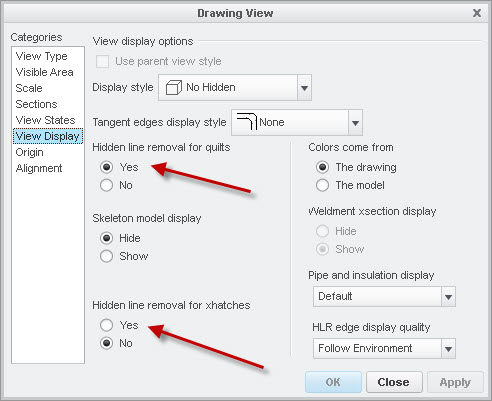
If it's a surface model and a x-section, you will also need to flip hidden line removal for xhatches and edit your x-section in the model to include quilts.
