
Turn on suggestions
Auto-suggest helps you quickly narrow down your search results by suggesting possible matches as you type.
Showing results for
Please log in to access translation
Turn on suggestions
Auto-suggest helps you quickly narrow down your search results by suggesting possible matches as you type.
Showing results for
Community Tip - Did you get called away in the middle of writing a post? Don't worry you can find your unfinished post later in the Drafts section of your profile page. X
- Community
- Creo+ and Creo Parametric
- 3D Part & Assembly Design
- Drawings unstable in Creo 2.0?
Translate the entire conversation x
Please log in to access translation
Options
- Subscribe to RSS Feed
- Mark Topic as New
- Mark Topic as Read
- Float this Topic for Current User
- Bookmark
- Subscribe
- Mute
- Printer Friendly Page
Drawings unstable in Creo 2.0?
Jun 22, 2012
02:28 AM
- Mark as New
- Bookmark
- Subscribe
- Mute
- Subscribe to RSS Feed
- Permalink
- Notify Moderator
Please log in to access translation
Jun 22, 2012
02:28 AM
Drawings unstable in Creo 2.0?
I just completed a very comprehensive machining drawing and I must say that between 2000i and Creo 2.0, the drawing had become seriously unstable.
1st I was dealing with some very annoying graphics artifacts. Ones where simply moving an annotation feature would blank out the feature. More often than not, I would have to regenerate the drawing to get things to unhighlight or come back to a visible state. Seriously annoying indeed!
Then I had whole blocks of dimensions and other features just -move-. They jumbled themselves up left and right generally undoing a lot of careful placement that I was -doing-. It happened sometime between switching to the model and drawing, and poof, I again had to fix a couple of dozen annotation features.
Am I the only one? ...or is this something that has become the norm? Seriously, in 2000i, it was set it and forget it. Now I don't know how people keep from pulling their hair out.
I am on an approved platform with the approved drivers... etc.
This thread is inactive and closed by the PTC Community Management Team. If you would like to provide a reply and re-open this thread, please notify the moderator and reference the thread. You may also use "Start a topic" button to ask a new question. Please be sure to include what version of the PTC product you are using so another community member knowledgeable about your version may be able to assist.
Labels:
- Labels:
-
General
141 REPLIES 141
Jul 17, 2012
02:45 AM
- Mark as New
- Bookmark
- Subscribe
- Mute
- Subscribe to RSS Feed
- Permalink
- Notify Moderator
Please log in to access translation
Jul 17, 2012
02:45 AM
Hi Antonius,
we are still in the piloting phase so the designers are still lacking real project experience but i think with a bit of practice they would manage to create a 3D annotated model in the same time as a drawing.
Ideally the drawing would then just be a by-product that merely requires minor adjustments. E.g. in WF4 when creating drawing views from 3D combined views some annotations lose their placement (in terms of layout) and need to corrected.
Jul 24, 2012
05:34 PM
- Mark as New
- Bookmark
- Subscribe
- Mute
- Subscribe to RSS Feed
- Permalink
- Notify Moderator
Please log in to access translation
Jul 24, 2012
05:34 PM
Hey Antonius...
I am going to go back through the rest of this thread and make sure I'm not giving an answer that's already been given. But did you ever manage to hide the datums?
I specifically installed Creo 2 today (and got a new license file) so I could check out the errors people have been posting. I started with your "Hide the Datum" part. I'll admit it was being a bit of a bear... but I did manage to hide it without toggling all annotations off.
Is this still an issue for you?
Thanks!
-Brian
Jul 07, 2012
03:45 AM
- Mark as New
- Bookmark
- Subscribe
- Mute
- Subscribe to RSS Feed
- Permalink
- Notify Moderator
Please log in to access translation
Jul 07, 2012
03:45 AM
Luckily with 99% of my projects I don't have to bother with geometric tolerances. I have to say that I didn't have to bother with that in Creo so far in the last half year. I brought Creo into our company at the beginning of this year.
I am simply not forced to apply geometric tolerances to my drawing because as you said it is very cryptic. Most of the people here doesn't even know how to read these tolerances.
And I think I wouldn't bother playing around with that in Creo because I find it utterly slow to define these. I don't even bother with any kind of annotation on model level. I define everything like that in drawings directly but surely the data then aren't very consistent.
But maybe I am wrong talking about things I've never tried saying they are utterly slow. 
Jul 07, 2012
04:28 AM
- Mark as New
- Bookmark
- Subscribe
- Mute
- Subscribe to RSS Feed
- Permalink
- Notify Moderator
Please log in to access translation
Jul 07, 2012
04:28 AM
Thanks Jakub. Indeed, the GD&T is a whole other animal when it comes to Pro/E. You are pretty much forced to use the model for assigning datums since you cannot create "feature control symbols" that relate back to datums without them. The contract I am on right now is absolutely GD&T all the way and I am having to go back to my old way of doing things... just draw them.
This is sad as PTC has spent years trying to perfect the paperless system. I can't get any fabricators to buy into this, but never the less, annotation is moving further and further from the drawing and into the model.
I have no qualms about using the model dimensions in my drawings... or even the model axis display on the drawings. For the most part, this works okay if you know about the circle axis setting in config.pro. Way to often my model dimensions will not re-associate in detail view and I happen to pattern the feature from somewhere else. Then too, I have a healthy habit of providing reference dimensions from view to view. of course, they are not in the model either. And I do like over/under limit dimensions which we have very little control over on the drawing so these need to be "faked" in also.
Making feature control symbols on the fly was always a tough one because the leaders never did what you wanted. I still have trouble with this and just place non-leader versions at the end of a dimension line. But the new ISO style datums are another thing. We can make the triangle attachment but I end up making all kind of drawing sketch features to make all this work for me. Hence, giving the new version a workout in the GD&T realm. And it still stinks, so much so that I couldn't help but report this one as a bug. One that crashed my system twice! Fortunately the tech was watching every move... even got him chuckling over the weird behavior. Of course, that made me nervous!
As for the cube with the persistent datum plane, it is not the part file, and it is not the drivers. It is indeed a bug. The datum tags are annotation so they switch on and off easily in the model through the graphics toolbar. The config.pro setting is the same as the datum switch in the graphics toolbar. yes, I turned everything off I could and no joy. You can re-create the very same thing I did with a new part and you will have the same problem. If not, please post the part and let me have a look.
Jul 09, 2012
11:24 AM
- Mark as New
- Bookmark
- Subscribe
- Mute
- Subscribe to RSS Feed
- Permalink
- Notify Moderator
Please log in to access translation
Jul 09, 2012
11:24 AM
hi Antonius,
I am surprised to see someone going the "all information should be in the 3D model" route. I really admire you for going this pretty tough path. I wish I could go the same way one day. I have much to learn there yet. How to possibly put all the necesarry annotations like notes related to manufacturing, roughness, sharpness/roundness  of inner and outter edges of the part, globally defined tolerances and so on. I don't think my company will ever try to manufacture parts without drawings even if I knew how it could be done, step after step but I would like to figure that out. Could be handy someday.
Anyway I've had a look at your part file today and I have got the same issue as you have. I am actually wondering how did you manage to hide the -B- datum plane cause I can't find out how to do that.
It's definetly a bug. I have been able to reproduce the issue on one of my models. The datum annotation tag renamed one of my datum planes in such a way so I am unable to change it back the way it was. It changed the datum plane tag to some floating note that doesn't show up till I select the plane. Which is pretty odd.
Glad to hear you were able to report this issue. So the devs might do something about it. In M010 they fixed one of bug I found in F000 and reported back then when it came out.
I am not able to report stuff directly to PTC anymore. Their website tells me to contact my VAR and my VAR is... well... so I am on my own now.
~Jakub
Jul 09, 2012
11:55 AM
- Mark as New
- Bookmark
- Subscribe
- Mute
- Subscribe to RSS Feed
- Permalink
- Notify Moderator
Please log in to access translation
Jul 09, 2012
11:55 AM
Thanks for your confirmation, Jakub.
As for paperless GD&T... it certainly is not my 1st choice. Nobody I know will use it and I work with a lot of high end fab shops. It is just the direction PTC has been working towards for over a decade. I just want to put my GD&T on the drawing where it belongs. Creo simply doesn't make it easy primarily due to their poor datum implementation.
I have been able to do everything else I needed to do with the model datums. Turning off annotation is simple; deleting the annotation returns the datum to classic datum styles [-A-]; and properties will let me change the datums back to "normal" datum planes.
The datums in drawings, on the other hand is absolutely unusable. Moving them, re-assigning them, even using the "SHOW ANNOTATION" is flacky for these as they show by default in -some- views.
Don't get me wrong... the annotation capabilites in the model are welcome. I use it for quite a few temporary measures on my imported models to quickly know what I am working with. But locking the datums specifically to model features for drafting purposes is a lot more work for PTC and the payback can only be a couple of bigwig customers who demand paperless systems. It doesn't work for drawings! That leaves the rest of us in the dust. I would really like to see a thorough and comprehensive tutorial on this. And each release, the S/W QC department should be made to test the tutorial steps and previously reported bugs with each new release. If anyone knows of such a tutorial, please link me up.
If you ever need verification, Jakub, for something that could be a bug, please let us know. I'm sure one of us can be just as annoyed and report it to tech support.
Jul 09, 2012
12:54 PM
- Mark as New
- Bookmark
- Subscribe
- Mute
- Subscribe to RSS Feed
- Permalink
- Notify Moderator
Please log in to access translation
Jul 09, 2012
12:54 PM
I'm actually surprised you guys are having so much trouble with the GD&T system and the paperless drawings. We've been using these for quite awhile... and using the NEW GD&T standard, too. We've gotten quite adept at making the look the way we want without much fighting.
Paperless drawings have been a dream for at least a decade. With the new annotation tools, it's compeltely possible to document manufacturing notes, surface finish details, global tolerances, etc within the model.
Back in 2001, I worked for a company that decided they were going paperless. We worked with vendors who agreed to accept our 3D annotated models and fabricate from them. The effort was completely successful. In the end, we did come back to making a limited dimension drawing for receiving purposes. Of all the roadblacks to hit, the accounting people were the ones who broke the process. They demanded a drawing... so we'd create a drawing with 3 ortho views with basic bounding dimensions and 1 isometric image. That's all we ever did and it worked well.
Over the years, the annotations have only gotten better. Even though we're nowhere near "paperless" at my current job, we build ALL GD&T into the models. If anyone tried to "fake" them, they'd be called on the carpet for it. Reference dimensions are also be placed directly in the model.
I like the idea of a comprehensive tutorial. But my advice here is... don't hold your breath waiting for one. I think we'd have better luck creating one ourselves (the user community). Maybe someone will volunteer to take a crack at it?
Jul 09, 2012
01:23 PM
- Mark as New
- Bookmark
- Subscribe
- Mute
- Subscribe to RSS Feed
- Permalink
- Notify Moderator
Please log in to access translation
Jul 09, 2012
01:23 PM
I'm glad someone is on board for paperless. I can totally see the purpose for paperless and I see the types of industries that would benefit greatly from it. Again, the annotation in the model is not the problem. It seems to be working fine. Translating that annotation 100% to the drawing is what is a real bear. With the bugs in the datum symbols alone makes this untenable. I've had two hard crashes just moving the datum tag on a drawing and corrupt drawing files.
Brian, what do you do about the datum planes that will not hide in the model? These gets really messy when you have a 100 part assembly and 2-3 datums stick out of at least half the parts. In previous employment, datum tags were visible all over the model assembly (pre-2000i) and it really made for messy models.
Jakub, I forgot to comment on the datums that do hide properly... they are system generated datum planes from the faces that you select. The only ones that do not hide properly are the datum planes you created and select for datum tags.
The best guide for what the system has to do is the ISO standards themselves. Until such time that Creo can actually do everything noted in the standard, it will never be 100%.
Brian, you have the best of the other half of the equation, and you define the exact example that I stated earlier, that PTC is catering to the big $ few in this effort. I saw this coming years ago and I applaud the effort. The problem lies with us who do need both, 100% drawings and extensive GD&T. Since the Paperless mandate is close to being met (if not fully), the 100% drawings part is not going to get nearly the same attention. I can only report the bugs I find and can reproduce. Even that is slow in response when it is a mission critical aspect of my current contract.
Brian, remind us again what version you are using?
Jul 09, 2012
01:27 PM
- Mark as New
- Bookmark
- Subscribe
- Mute
- Subscribe to RSS Feed
- Permalink
- Notify Moderator
Please log in to access translation
Jul 09, 2012
01:27 PM
...and yes, the beancounters and quality control are the holdbacks in paperless systems in my industry. When your suppliers are "partners" in every sense, legal and quality, paperless is viable.
Jul 20, 2012
06:27 PM
- Mark as New
- Bookmark
- Subscribe
- Mute
- Subscribe to RSS Feed
- Permalink
- Notify Moderator
Please log in to access translation
Jul 20, 2012
06:27 PM
I know this is completely irrelevant by now but I meant to reply to this thread. It just kind of got out of hand for me. I was overwhelmed with other work and suddenly this thread had so many replies and nuances, I couldn't stay current without dropping other tasks.
So- I apologize for abandoning the conversation!
Right now we're running Creo Elements Pro/5 (Wildfire 5). We're migrating to Creo Parametric 1.0 in the coming weeks. We've been prepping for this for quite awhile.
At one point Antonius asked what we do about datums that don't hide in the model. I can honestly say I have never had this problem. I've always been able to layer off a datum, an annotation, or any other item I wish. I've never encountered the issue reported in this thread. Because I am not running Creo 2.0, I couldn't open the test part to reproduce it.
Anyway... this is a stale response to a very long thread. I just hate to leave questions unanswered if I can possibly help it!
Jul 20, 2012
06:44 PM
- Mark as New
- Bookmark
- Subscribe
- Mute
- Subscribe to RSS Feed
- Permalink
- Notify Moderator
Please log in to access translation
Jul 20, 2012
06:44 PM
Thank you, Brian. No worries!
Your reply is never the less welcome. I am still trying to make a case that this is "not" normal behavior and this problem not existing in Creo 1.0 is exacly the kind of input I need to keep drivng this issue. I will see if they gave it any thought with the next revision... if it is, I will report it again.
I just had it happen again in a production part. Very annoying.
Jul 09, 2012
03:10 PM
- Mark as New
- Bookmark
- Subscribe
- Mute
- Subscribe to RSS Feed
- Permalink
- Notify Moderator
Please log in to access translation
Jul 09, 2012
03:10 PM
This is a great image...

Jul 09, 2012
03:58 PM
- Mark as New
- Bookmark
- Subscribe
- Mute
- Subscribe to RSS Feed
- Permalink
- Notify Moderator
Please log in to access translation
Jul 09, 2012
03:58 PM
Great Job, Antonius. I've to applaud.
Brian. I am kind of new to parametric CAD environment. I chose to start with Creo Parametric about year ago (Pro/E WF5 Schools last year). Still digging around and juggling with the info that is given to me on a silver platter.
I should start with a CAD that is simpler and that offers more sound for less money but I was stub enough to go with Creo. Sometimes I think I would be way ahead considering productivity if I chose to go with Solidworks or Inventor even tho I call these "toys for kids".
But I think this will turn out well for me once I figure out how to automate most of my tasks.
3D annotations is not my priority atm since the demand for it over here equals to zero. But I am sure curious about learning it.
~Jakub
Jul 09, 2012
06:23 PM
- Mark as New
- Bookmark
- Subscribe
- Mute
- Subscribe to RSS Feed
- Permalink
- Notify Moderator
Please log in to access translation
Jul 09, 2012
06:23 PM
...that's not my work but I appreciate the effort someone put into it.
Jakub, the problem is that we are pretty much forced to use the model annotation -if- we want to use the full featured GD&T module.
Jul 11, 2012
12:30 PM
- Mark as New
- Bookmark
- Subscribe
- Mute
- Subscribe to RSS Feed
- Permalink
- Notify Moderator
Please log in to access translation
Jul 11, 2012
12:30 PM
ok, I see
I've found the Pro/E tutorial for annotations with this picture.
Jul 09, 2012
03:01 PM
- Mark as New
- Bookmark
- Subscribe
- Mute
- Subscribe to RSS Feed
- Permalink
- Notify Moderator
Please log in to access translation
Jul 09, 2012
03:01 PM
DAMN! Crashed again moving a datum tag in a drawing. All unsaved data lost. 
-------------------------------------------------
The datecode is: 2012130
The pro machine type is: x86e_win64
The process ID is: 6652
-------------------------------------------------
Exception EXCEPTION_ACCESS_VIOLATION has occurred in the thread 4724.
Main Thread 4724
=====================
0x00000001407502EE NULL (NULL:0) (xtop:0x000000013F150000) ( 0x1e255408, 0x1e255408, 0x7, 0x1ebe1388 )
0x0000000140707459 NULL (NULL:0) (xtop:0x000000013F150000) ( 0x1e255408, 0x0, 0x3940a440, 0x0 )
0x000000014070962F NULL (NULL:0) (xtop:0x000000013F150000) ( 0x95dce8, 0x95dd10, 0x2, 0x1e255138 )
0x0000000140AB064A NULL (NULL:0) (xtop:0x000000013F150000) ( 0x1, 0x329f678, 0x2886d500, 0x1 )
...<snip>
Jul 12, 2012
09:43 PM
- Mark as New
- Bookmark
- Subscribe
- Mute
- Subscribe to RSS Feed
- Permalink
- Notify Moderator
Please log in to access translation
Jul 12, 2012
09:43 PM
Just an update on my end. The recent update from NVidia for the 3000M card in my Dell Precision M6600 caused me flash player issues and the Dell tech support had me reload the original driver (almost a year old) which is only 1 generation up from the approved platform at PTC. So I loose all the PTC updates to NVidia as well.
Having done this, I am now one more drawing further in my pain we call Creo Detailing.
I finally narrowed down the crash problem with datum tags. It is now in the hands of PTC for resolution.
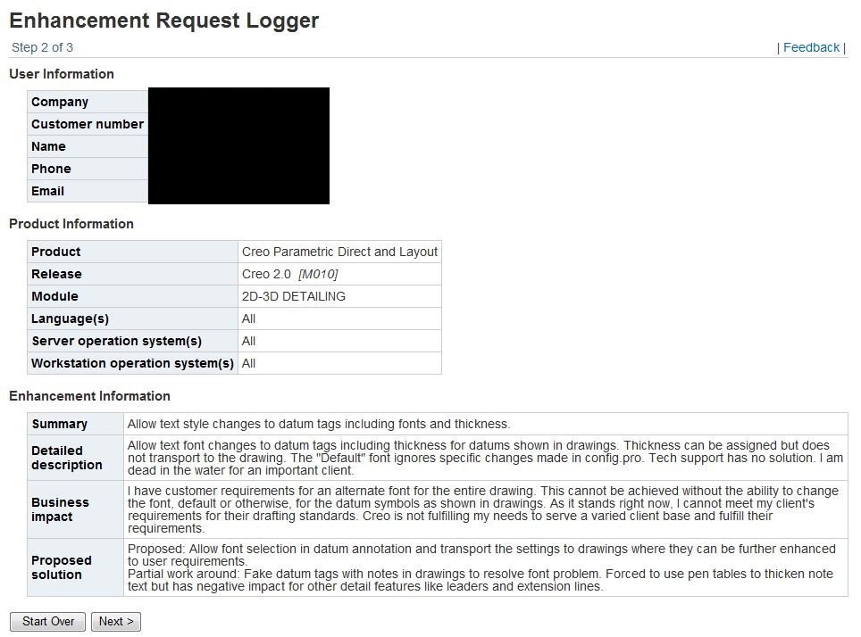
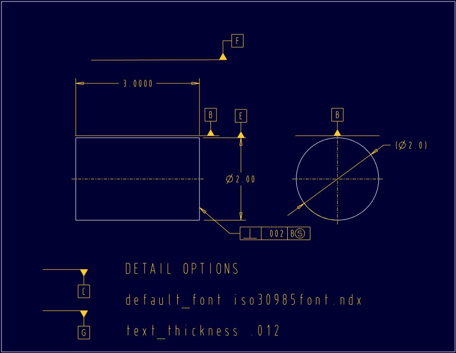
I also added a new service call with regard to not being able to change the text style of the datum tags in the drawing (haven't tested model GD&T yet). My customer demands a different font from default and an applied "thickness". The text font cannot be changed at this point and the thickness, when assigned in the model, does not transport to the drawing. in the drawing, you cannot access the datum tag text properties. Rock and a hard place! And on top of that, the axial datum tag text comes out bold while planer datum tags come out with thickness "0.000000" on the screen.
I have also learned that we cannot fake the appropriate datum tags (triangle leader) on horizontal surface (horizontal in reference to the drawing). If you make this a note, it forces an elbow. This is not allowed by the standards.

...and I have gleaned that drafting datums and annotation does not generate the new style datum tags. This needs further investigation, but it appears that the symbol above is not even addressed in the drafting GD&T module.
I should start a blog 
Jul 12, 2012
09:51 PM
- Mark as New
- Bookmark
- Subscribe
- Mute
- Subscribe to RSS Feed
- Permalink
- Notify Moderator
Please log in to access translation
Jul 12, 2012
09:51 PM
And since I am having so much trouble transporting the model GD&T from the model (crashing and corrupt drawing files), another limitation presented itself in making composite feature control frames in the drawing...
These cannot be duplicated with the text editor. Remember, I am charged with making "certified" drawings. This means it must meet the standards in -every- way.
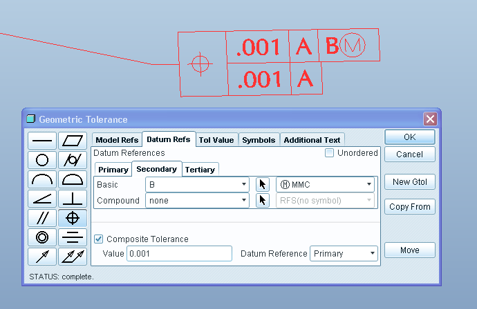
...image compliments of our own Brian Martin.
Jul 13, 2012
01:41 PM
- Mark as New
- Bookmark
- Subscribe
- Mute
- Subscribe to RSS Feed
- Permalink
- Notify Moderator
Please log in to access translation
Jul 13, 2012
01:41 PM
Ok, I was gonna suggest that you could always try to go define those tags as symbols. That alone wouldn't be too hard.
But defining every such compound geometric tol as the one shown on Brian's picture would be a huge painfull PAIN.
Still a way to go.
If you ask me I would be in AutoCAD after the two first miliseconds just thinking about this.
Jul 13, 2012
01:59 PM
- Mark as New
- Bookmark
- Subscribe
- Mute
- Subscribe to RSS Feed
- Permalink
- Notify Moderator
Please log in to access translation
Jul 13, 2012
01:59 PM
I'm up to 10 support issues and counting. Several have gone into SPR limbo. I hope Brian has more luck in the Detailing Committee.
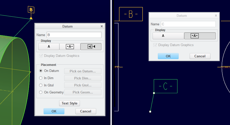
Found a new one this morning... Drafting datum tags does not support the ANSI Y14.5 1994 datum symbol.
The left is the model annotation "properties" editor... and the right is a drafting datum and the "properties" editor.
I simply can't win this one. I have a deadline and the limitations are simply overwhelming.
Jul 13, 2012
02:10 PM
- Mark as New
- Bookmark
- Subscribe
- Mute
- Subscribe to RSS Feed
- Permalink
- Notify Moderator
Please log in to access translation
Jul 13, 2012
02:10 PM
...11 support issues 
Jul 13, 2012
02:25 PM
- Mark as New
- Bookmark
- Subscribe
- Mute
- Subscribe to RSS Feed
- Permalink
- Notify Moderator
Please log in to access translation
Jul 13, 2012
02:25 PM
Hmm, maybe theres a setting in *.dtl file that could switch that? Maybe yours is set to ASME standart somewhere?
EDIT: Yeap, its called gtol_datums I guess.
Jul 13, 2012
03:19 PM
- Mark as New
- Bookmark
- Subscribe
- Mute
- Subscribe to RSS Feed
- Permalink
- Notify Moderator
Please log in to access translation
Jul 13, 2012
03:19 PM
Aha!... yes, that works, but still has the same problems as making "fake" note datums... It will not attach with only the vertical line and no leader. In close reading of the ANSI/ASME Y14.5 1994 text, the horizontal leaders are allowed so all I have to do is convince my client that this is acceptable to the standards. Like I really like telling my customers that they are wrong
And I still can't change the text style. According to tech support, not changing text style is expected behavior. They cannot put in an SPR for this and the recommended route is to submit an "IDEA" here in the forum. DO WHAT! Like that's going to go anywhere.
I am getting seriously annoyed with how PTC is handling the shortcomings of their detailing capabilities. I am -very- glad my client decided to turn down the opportunity to upgrade CoCreate to Creo/Pro. That would have been a really bad move after seeing what I am dealing with in regard to both support and Creo capabilities.
Jul 13, 2012
03:38 PM
- Mark as New
- Bookmark
- Subscribe
- Mute
- Subscribe to RSS Feed
- Permalink
- Notify Moderator
Please log in to access translation
Jul 13, 2012
03:38 PM
Ok, I am not at work to try this in Creo right now but I am almost sure that if you can't change the text font of the geom tolerance though RMB --> Properties menu then you can change it globally within your *.dtl file.
The option to change that is called default_font and you can choose any font you like that is in the .../text/fonts/ folder in the instalation path of Creo or you can set pro_font_dir in your config.pro and move the folder elsewhere that way.
Not sure what do you mean by horizontal and vertical attachment lines. I have no idea how to really properly define a fake note datum. I remember that I once managed to define a model datum axis to a hole of an imported model from inside the drawing. It was pretty cool but I dont use that way to create axes anymore since I know about hole recognition tool which is much faster when theres more than just a few holes.
Good luck.
Jul 13, 2012
03:59 PM
- Mark as New
- Bookmark
- Subscribe
- Mute
- Subscribe to RSS Feed
- Permalink
- Notify Moderator
Please log in to access translation
Jul 13, 2012
03:59 PM
Thanks again, Jakub.
Indeed, changing the default font and thickness would be fine with me but someone mentioned this didn't work either. I tried making this change and dimensions stopped being created in the drawing.
I submitted an enhancement request but not sure if it went anywhere since I am not a platinum member appearantly. So I added THIS idea as well. Please vote!
Jul 13, 2012
04:16 PM
- Mark as New
- Bookmark
- Subscribe
- Mute
- Subscribe to RSS Feed
- Permalink
- Notify Moderator
Please log in to access translation
Jul 13, 2012
04:16 PM
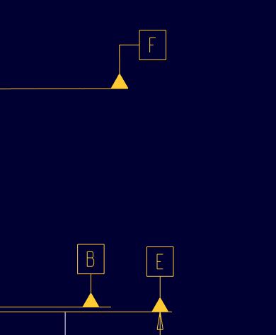
Tail [F] = drafting datum - No-Tail [B] & [E] = model datum
Customer requires no tails. And who am I to argue with the customer?
Jul 14, 2012
03:53 AM
- Mark as New
- Bookmark
- Subscribe
- Mute
- Subscribe to RSS Feed
- Permalink
- Notify Moderator
Please log in to access translation
Jul 14, 2012
03:53 AM
Not sure whats going on there. I would just try to completely reinstall Creo.
The global settings of fonts in *.dtl file should work the way I described.
You can change thinkness of all *.ndx fonts but not *.ttf fonts. You should be able to use model tags and move them in drawing without crash or whatever.
Also if you are gonna assing a datum tag on a model level then try to assing it to a geometry surface directly. Not a datum surface.
No-tail for a datum tag is the standard. At least that what I was told in school. Wondering what the other one with tail even does there.
Jul 14, 2012
10:21 AM
- Mark as New
- Bookmark
- Subscribe
- Mute
- Subscribe to RSS Feed
- Permalink
- Notify Moderator
Please log in to access translation
Jul 14, 2012
10:21 AM
An elbow is allowed by Y14.5 so it's preference as to whether or not you use it although you may not see as many examples with it. Looking at your picture though it appears your draft datum is not perfectly horizontal (you can see that the extension line is slightly jagged) but has a slight angle to it which would account for the tail.
Jul 14, 2012
02:05 PM
- Mark as New
- Bookmark
- Subscribe
- Mute
- Subscribe to RSS Feed
- Permalink
- Notify Moderator
Please log in to access translation
Jul 14, 2012
02:05 PM
Okay, you guys ROCK!
Good eye, Kevin. Indeed the datum was not horizontal and that caused the issue. I was so frustrated it didn't even dawn on me. When I keyed in the datum, it worked as expected.
Y14.5 probably allows the horizontal tail because it has to do this for angled surfaces. That is normal behavior.
Jakub, I was trying to set the font in the config.pro. Default_font in config.pro is something completely different.
I think I confused the system when I specified the fond and failed to put the .ndx on the end. It was added by default but this caused the system to misbehave and ignored adding drafting dimensions.
THE GOOD NEWS IS... that the part/assembly default text is overwritten by the detail options (.dtl). All text tagged with a "default" style will take on the new attributes, including model annotation, which is exactly what I wanted all along.
Now I have to test all this in my next drawing. Wish me luck!
I have sent in 2 complete file sets to the case that was submitted as an SPR. They should have enough evidence to resolve this issue. I can make it crash "out of the box" and that is one of the files I submitted.
I have a very clean install since I did the Creo 2.0 M010 update from scratch. I also had the same experience with 2 different revs of the graphics drivers. The platform is brand new and supported by PTC. I've put enough time into this to let them work on it now. I had enough trouble getting support to file the SPR to begin with.
Jul 16, 2012
12:19 PM
- Mark as New
- Bookmark
- Subscribe
- Mute
- Subscribe to RSS Feed
- Permalink
- Notify Moderator
Please log in to access translation
Jul 16, 2012
12:19 PM
Yesterday I was finally able to do a drawing 100% to customer expectations.
Certainly not to how PTC would prefer I use the software, but the drawing was per customer requirements.
Small steps and all that.
This is now 3 weeks after I started this thread.
Maybe someone at PTC can address "this" customer's experience in learning why the usability of this software is really lacking. I've been working full time on Creo 2.0 since late May. ...And I am not a newbee to Pro/E.
This has been very painful and quite expensive in lost productivity.


