
Turn on suggestions
Auto-suggest helps you quickly narrow down your search results by suggesting possible matches as you type.
Showing results for
Please log in to access translation
Turn on suggestions
Auto-suggest helps you quickly narrow down your search results by suggesting possible matches as you type.
Showing results for
Community Tip - If community subscription notifications are filling up your inbox you can set up a daily digest and get all your notifications in a single email. X
- Community
- Creo+ and Creo Parametric
- 3D Part & Assembly Design
- Re: Dual Dimension GD&T Display
Translate the entire conversation x
Please log in to access translation
Options
- Subscribe to RSS Feed
- Mark Topic as New
- Mark Topic as Read
- Float this Topic for Current User
- Bookmark
- Subscribe
- Mute
- Printer Friendly Page
Dual Dimension GD&T Display
Aug 20, 2012
03:12 PM
- Mark as New
- Bookmark
- Subscribe
- Mute
- Subscribe to RSS Feed
- Permalink
- Notify Moderator
Please log in to access translation
Aug 20, 2012
03:12 PM
Dual Dimension GD&T Display
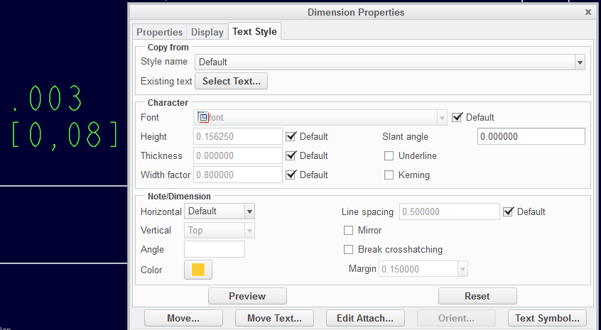
I'm dual dimensioning a drawing on 3.0 and running into an issue when adding a GD&T block where my primary - inch tolerance is to 3 places. I need the secondary - mm tolerance, to display two places, IE: .003[.08]... I achieved this by using dual_digits_diff in the options, but my problem is that it just cuts off everything after the second place in the [secondary]. This is what it's displaying ".003[.07]". Essentially, what I need it to do is round up from .0762mm to .08mm. Any ideas?
This thread is inactive and closed by the PTC Community Management Team. If you would like to provide a reply and re-open this thread, please notify the moderator and reference the thread. You may also use "Start a topic" button to ask a new question. Please be sure to include what version of the PTC product you are using so another community member knowledgeable about your version may be able to assist.
Labels:
- Labels:
-
2D Drawing
18 REPLIES 18
Aug 20, 2012
06:10 PM
- Mark as New
- Bookmark
- Subscribe
- Mute
- Subscribe to RSS Feed
- Permalink
- Notify Moderator
Please log in to access translation
Aug 20, 2012
06:10 PM
I take it back... mine is rounding up on .003...
Creo 2.0 M010
Aug 21, 2012
10:48 AM
- Mark as New
- Bookmark
- Subscribe
- Mute
- Subscribe to RSS Feed
- Permalink
- Notify Moderator
Please log in to access translation
Aug 21, 2012
10:48 AM
Antonius, I get the same on regular dimensioning, but I'm talking about within a GD&T block..
The Primary is set to 3 places but the secondary is just cutting off the digits past two places, so instead of rounding up to .08mm from .0762, it just displays [0.07]
Aug 21, 2012
11:32 AM
- Mark as New
- Bookmark
- Subscribe
- Mute
- Subscribe to RSS Feed
- Permalink
- Notify Moderator
Please log in to access translation
Aug 21, 2012
11:32 AM
Thanks for the clarification. Indeed, this is still an issue in Creo 2.0 M010. Thanks for the heads up.
I will report this to CS and see what they have to say. Yet another reason -not- to use GTOL! 
"BRIAN!"
Oct 06, 2012
08:26 PM
- Mark as New
- Bookmark
- Subscribe
- Mute
- Subscribe to RSS Feed
- Permalink
- Notify Moderator
Please log in to access translation
Oct 06, 2012
08:26 PM
Ah... you know it really stings when I see someone ask for my help by name and I'm not around to answer. It's like Batman not answering the bat signal!
lol... anyway, Antonius I think you did a great job digging into this one. You found a bug... or if not a true bug at least a great opportunity for an enhancement. With Wildfire 5, PTC finally gave us great options for rounding secondary dimensions. I had no idea the GTOL secondary dimensions had any limitations at all.
Thanks for working on this and following it up. What do we need to pursue this further? The PTC Technical Committee meetings are coming up in January. If this is something we need to address, I'll be happy to take it to the meeting and get it in front of the developers and other TC group members.
Thanks... and sorry I wasn't around when this initially came up!
-Brian
Oct 06, 2012
08:53 PM
- Mark as New
- Bookmark
- Subscribe
- Mute
- Subscribe to RSS Feed
- Permalink
- Notify Moderator
Please log in to access translation
Oct 06, 2012
08:53 PM
No problem, Brian. I too was taken out of this community for about 3 weeks due to "obligations" and happy to see your smiling avatar back at it.
In this case, yes, PTC did due diligence but only half way. It appears, and I do not have the reference, but it appears that there are more than one way to skin this cat. I have seen many references since that simply round appropriately and do not round down to the minimal tolerance.
You will probably need to be armed with SAE J390 to make a case. Somehow I think you just might have access to that 
Oct 06, 2012
11:33 PM
- Mark as New
- Bookmark
- Subscribe
- Mute
- Subscribe to RSS Feed
- Permalink
- Notify Moderator
Please log in to access translation
Oct 06, 2012
11:33 PM
It's crazy how things can go from manageable to overwhelming in the blink of an eye. Luckily things have calmed down again and I'm starting to dig out from under the pile of work that was burying me.
I'm going to flag this message in my email and come back to it when I'm at NASA on Monday. We have IHS (which is a tremendous resource for standards) and we might just have access to all of the SAE standards. I know we have access to a huge volume of documents- I'll do a search for SAE J390 and see what comes up.
Have a great weekend...
Aug 21, 2012
03:24 AM
- Mark as New
- Bookmark
- Subscribe
- Mute
- Subscribe to RSS Feed
- Permalink
- Notify Moderator
Please log in to access translation
Aug 21, 2012
03:24 AM
I think I know the answer to this one...
I'm guessing this is a maximum limit.
Your primary dimension is inches, .003.
If the secondary dimension in mm was shown as 0.08, that would be .00315 - but this is greater than the max tolerance you've specified in your primary dimension.
Therefore, to 2dp the mm dimension can only be 0.07, otherwise it could be out of limit per your primary dimension.
Aug 21, 2012
10:51 AM
- Mark as New
- Bookmark
- Subscribe
- Mute
- Subscribe to RSS Feed
- Permalink
- Notify Moderator
Please log in to access translation
Aug 21, 2012
10:51 AM
Yes, unfortunatly I think you are correct on this one. The problem is, when it comes to the machining to 3 places for mm, it's the same as machining to 4 places for inch... that gets quite expensive...
Aug 21, 2012
10:52 AM
- Mark as New
- Bookmark
- Subscribe
- Mute
- Subscribe to RSS Feed
- Permalink
- Notify Moderator
Please log in to access translation
Aug 21, 2012
10:52 AM
of course we could do well to avoid the issue all together and covert the entire planet over to metric as it should be. 
Aug 21, 2012
10:57 AM
- Mark as New
- Bookmark
- Subscribe
- Mute
- Subscribe to RSS Feed
- Permalink
- Notify Moderator
Please log in to access translation
Aug 21, 2012
10:57 AM
Only if you're using a system which relates the tolerance to the number of displayed decimal places... otherwise machining to 0.995/0.795 is no harder than machining to 1.0/0.8. 0.9 satisfies either of them!
And in the case of your GD&T, machining to 0.076 is definitely (slightly) easier than machining to 0.07.
Aug 21, 2012
12:13 PM
- Mark as New
- Bookmark
- Subscribe
- Mute
- Subscribe to RSS Feed
- Permalink
- Notify Moderator
Please log in to access translation
Aug 21, 2012
12:13 PM
John, again, thank you for bringing this up as this will certainly be a problem I will run into. I have been very diligent in learning how to make model annotation work for me in my contract design business. This is yet another stumbling block.
I have reported this to CS and created an Idea (bug report!) that needs a flood of votes if you can access the Ideas section. Below is a cross-post of the idea for those who cannot access it:
This really shouldn't be an Idea, but rather a "Quality Oversight Bulletin!".
This error should never have existed outside the halls of PTC, much less considered for release into production.
Why is it that dual dimensions round properly, yet GTOL dual dimensions truncate the secondary dimension?
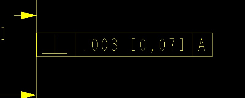
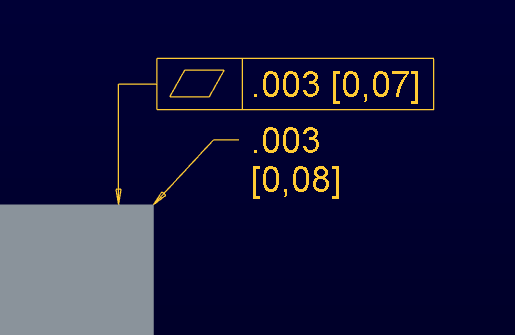
I will let the image speak for itself... ref - .0030 [0,07620]
model annotation shown.
detail config options:
dual_digits_diff -1
dual_dimensioning primary[secondary]
dual_secondary_units mm
This makes for yet another obstacle in 3D annotation not to mention using relational GTOL throughout development.
Aug 21, 2012
12:36 PM
- Mark as New
- Bookmark
- Subscribe
- Mute
- Subscribe to RSS Feed
- Permalink
- Notify Moderator
Please log in to access translation
Aug 21, 2012
12:36 PM
Thanks!
Aug 21, 2012
01:41 PM
- Mark as New
- Bookmark
- Subscribe
- Mute
- Subscribe to RSS Feed
- Permalink
- Notify Moderator
Please log in to access translation
Aug 21, 2012
01:41 PM
CS confirmed that this is expected behavior only with regard to tolerances. I have requested ASME and ISO references to confirm this complies to standards. Jonathan's explanation is what seems to be the guiding factor.
Title
Tolerance values of Secondary Units are tighter than Primary Units in Creo Parametric
Description
- With Dual Dimensioning, Tolerance values of Secondary Units are rounded incorrectly.
- The Secondary Dimension tolerance values are Truncated instead of rounding
- Why are the secondary units rounded differently than the primary?
Applies To
- All releases of Pro/ENGINEER and Creo Elements/Pro
- Creo Parametric 1.0, 2.0
Cause
- Works to Spec
Resolution
- Secondary values are rounded to fit within the range indicated by primary units
- See also Help files at #Help# Help Center > <Product> Functional Areas > Detailed Drawings > Detailed Drawings > Annotating the Drawing > Dimensioning the Model > Formatting Dimension Display > To Format Existing Dual Dimensions in a Drawing.
- Product Help Extract:
Note
"When you are using dual dimensioning with dimensional tolerances, the system rounds the secondary values so that they always fit within the range indicated by primary units (that is, so that they are tighter than primary values), and retain the desired design intent".
Of course, this opens another can of worms... what dimension is the "valid" dimension? I always considered the secondary to be a "reference". Regardless, the primary must be met. Am I wrong in the words of ASME and ISO? If I thought about it hard enough, can't you make a dimension contradict the limits by rounding the secondary (nominal secondary + tolerance range compared to primary range)? Calling on you mathmatiocians here
Regardless, this seems odd until I find out more. Clients tend to have rules that don't always conform to standards. At the very least, this should a config option.
Idea edited.
Aug 21, 2012
12:20 PM
- Mark as New
- Bookmark
- Subscribe
- Mute
- Subscribe to RSS Feed
- Permalink
- Notify Moderator
Please log in to access translation
Aug 21, 2012
12:20 PM
BTW: Your work-around is to use text notes rather than GTOL. The only time you will run into serious trouble is when you need to make a composite tolerance block with the ill-rounding of the dual dimension.
If you want to use mixed-mode dual dims in GTOL (use GTOL where the conversion is valid) then you will have to manually evaluate each conversion to make sure it rounded properly. For those in error, you will need to make a note. Heaven help anyone that has to sustain that drawing, however.
Aug 21, 2012
02:46 PM
- Mark as New
- Bookmark
- Subscribe
- Mute
- Subscribe to RSS Feed
- Permalink
- Notify Moderator
Please log in to access translation
Aug 21, 2012
02:46 PM
A little more research shows that dual dimensioning is governed by SAE J390 (1999).
Does anyone have access to this standard? Please weigh in as I need more evidence to support the "idea" as a viable config option.
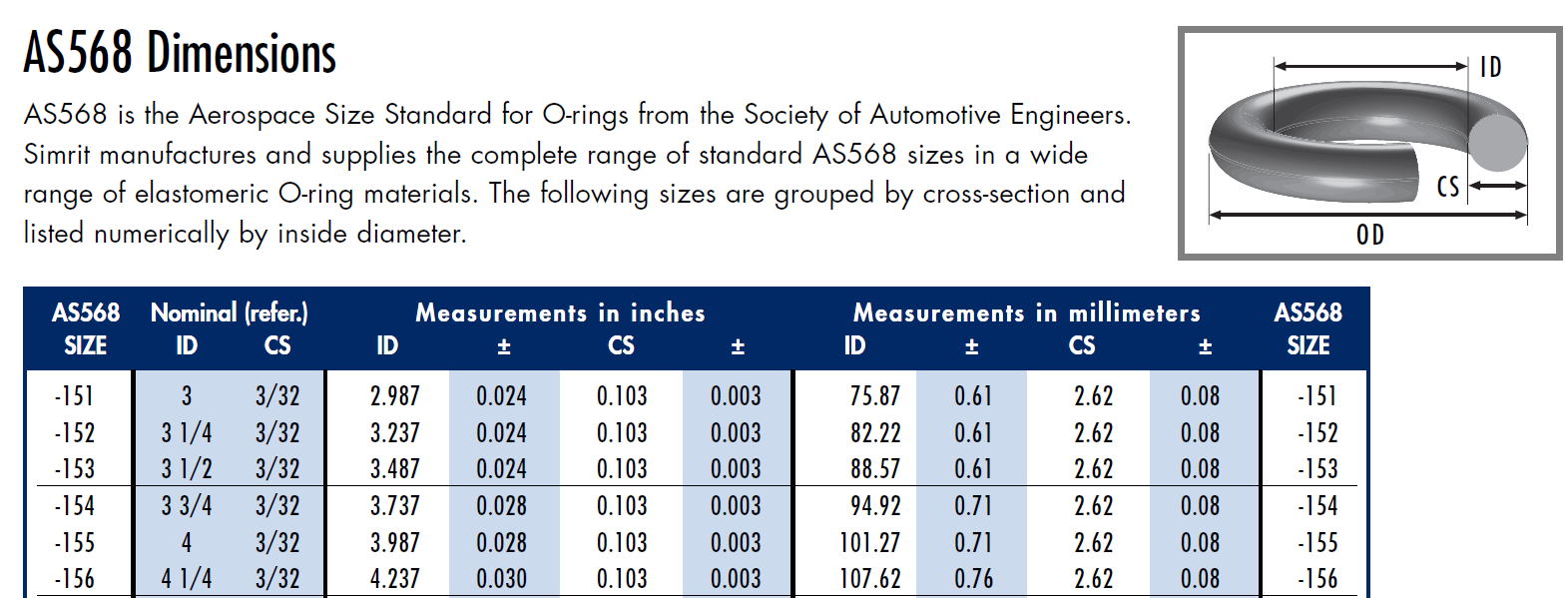
Anyway, I found the following information on All-Seals Inc web site. Please note they refer to "method A" per the standard. Below is their statement regarding dual dimension references and an example of a .003" tolerance.
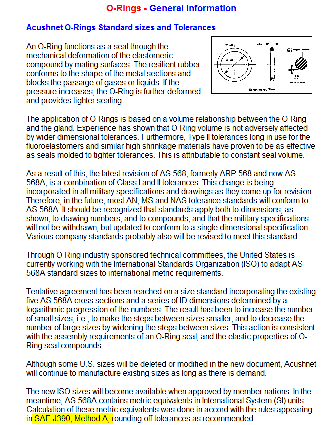
This document seems to guide ASME more than ISO. But according to these findings, there is a legitimate call for having the option to properly round the value vs always rounding to minimal.
Additional comment added to the Idea.
Mar 27, 2013
02:57 PM
- Mark as New
- Bookmark
- Subscribe
- Mute
- Subscribe to RSS Feed
- Permalink
- Notify Moderator
Please log in to access translation
Mar 27, 2013
02:57 PM
Well about 9 months after the fact our company approached the same problem.
The post about "
Note
"When you are using dual dimensioning with dimensional tolerances, the system rounds the secondary values so that they always fit within the range indicated by primary units (that is, so that they are tighter than primary values), and retain the desired design intent"."
is correct I received a similar answer from PTC tech support.
ASME Y14.5M -1994/ 2006 Does not mention or support Dual dimensions.
“ASME Y14.5M, that wording is as such in 1.4(d), “Dimensions shall be selected and arranged to suit the function and mating relationship of a part and shall not be subject to more than one interpretation.”
General practice in the use of dual dimensions is that they are of equal importance to the primary dimension. This creates issues in that it allows for more than one interpretation of the dimension. It is nearly impossible for nominals and tolerance ranges to be identical between units of measure. This means that the dual dimension tolerance range is usually resized to fit within the tolerance range of the primary unit of measure. This creates a situation where the dimension has more than one interpretation, which is specifically prohibited by 1.4(d).”
I found a copy of SAE J390, and I didn't find any special way of rounding that would interpret this.
Hope this helps.
And from anyone else reading this post. This is the design of PRO-E, and probably not something that should be over ridden.
Mar 27, 2013
03:49 PM
- Mark as New
- Bookmark
- Subscribe
- Mute
- Subscribe to RSS Feed
- Permalink
- Notify Moderator
Please log in to access translation
Mar 27, 2013
03:49 PM
Thank you for reviewing this. Can you state what Method A states in the SAE J390 document?
Mar 27, 2013
03:55 PM
- Mark as New
- Bookmark
- Subscribe
- Mute
- Subscribe to RSS Feed
- Permalink
- Notify Moderator
Please log in to access translation
Mar 27, 2013
03:55 PM
I didn't see anything in particular about method A. I found a copy of the standard here.
http://www.docin.com/p-112267509.html
The website is entirely not in English, but the PDF is. I somehow got it to show the individual pages and take screen caps of them, then printed it out.


