Community Tip - New to the community? Learn how to post a question and get help from PTC and industry experts! X
- Community
- Creo+ and Creo Parametric
- 3D Part & Assembly Design
- Re: Dual dimension issue
- Subscribe to RSS Feed
- Mark Topic as New
- Mark Topic as Read
- Float this Topic for Current User
- Bookmark
- Subscribe
- Mute
- Printer Friendly Page
Dual dimension issue
- Mark as New
- Bookmark
- Subscribe
- Mute
- Subscribe to RSS Feed
- Permalink
- Notify Moderator
Dual dimension issue
Hi all,
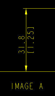
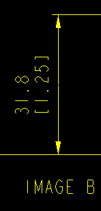
just recently i started working with dual dimension (metric primary, imperial secondary units). I have an issue with just one drawing out of a set of around 15. The issue is how the dual dimension is displayed, i want where possible both values displayed side by side, above the leader line & so i have the config option parallel_dim_placement set to above. Now the option states "does not apply to dual dimensions", but on this particular drawing it does. I have gone through the drawing set-up files for both this drawing & one of the others that is behaving the way i want, & they appear identical. I have attached some screen shots, images 1 & iA are how i would like to display my dimensions, image 2 is what i am getting on this one drawing. This must be a config option i have over looked, any ideas?
Regards
John
This thread is inactive and closed by the PTC Community Management Team. If you would like to provide a reply and re-open this thread, please notify the moderator and reference the thread. You may also use "Start a topic" button to ask a new question. Please be sure to include what version of the PTC product you are using so another community member knowledgeable about your version may be able to assist.
- Labels:
-
2D Drawing
- Mark as New
- Bookmark
- Subscribe
- Mute
- Subscribe to RSS Feed
- Permalink
- Notify Moderator
Select all Dim.
go to
Dim. properties
in Dual Dim (bottom right corner)
change position (to right)
Problem solved.
You can do it for all dim. or for any perticular dim. depends on req.
Enjoy.
- Mark as New
- Bookmark
- Subscribe
- Mute
- Subscribe to RSS Feed
- Permalink
- Notify Moderator
Hi Ganesh,
yes, i am already aware of this function. The issue is the config option i mentioned, the same setting appears to give different results depending upon what drawing i open. I have the option set to above & on the majority of my drawings i get what you see in image A (which is what i require) but in one or two of my drawings the same setting "above" gives what you see in image B. I use the same drawing option file for all my drawing requirements, so i cannot understand why this is happening.
Regards
John


