

Dynamic Sketches - VSS Discussion
For those of you who work with variable section sweeps, one of the options in the Sweep feature, you know just how finicky this command can be. The problem is two-fold; one - the trajpar statement in Relations has to be logical based on the trajectory type, and two - is the validity of the section though the full range of the variable parameter.
For case one: The trajpar... or trajectory parameter, is simply a value. Yet, it depends on the type of trajectory selected to know how to formulate the trajpar statement in Relations. The variable trajpar is simply a value from 0 to 1. Rules for using trajpar is different depending on the type of trajectory is selected. All trajectories yield a value of 0 at the beginning and 1 at the end. Logical enough. This simply means that -along the trajectory- the value increases linearly from 0 to 1 depending on how far along the chosen trajectory the sketch has "evolved". This is a very simple rule to follow for open trajectories. The variable trajpar can be used in any valid formula in the Relations of the VSS sketch in which it is called. However! when you choose a closed trajectory, things seem to change. Many trajpar statements seem to fail. Consider a simple vertical line swept along a circle. You add the statement "d(n)=1+trajpar", you would expect the line to sweep along the circle and increase from length 1 to length 2 from the beginning to the end of the circle. For some reason this is not logical to the programmers because the ends would not meet seamlessly. So you might consider the trajpar statement -requires- the end condition to be the same as the beginning in the case of closed trajectories. This is most often resolved by using sine curves to ensure the end condition of the profile sketch is equal to the beginning.
For case two: Sketch validity is much more problematic. Just as when you drag a sketch, the Solver seems to suddenly suffer brain-freeze at the most peculiar times. The Solver finds two solutions, or a paradox in the evaluation. Lines jump from one side to the other; they inverse; circles become zero, or worse, infinity. Angles simply reverse geometries at 180 degrees. Something should really be done about this in Sketcher but for the time being, we have to outwit the Solver. This is not easy, but we must manage if we wish to have solid and reliable variable section sweeps. Ambiguity is simply not allowed! As for rules, the Relation statement using trajpar -cannot- allow values to go negative. Whatever you use the range 0 - 1 for, it -must always- return a positive value or zero. Yes, zero is allowed! Line length=zero is allowed; angle=zero is allowed; Even circles can ...=zero! But in no instance does a negative value work. It simply fails the sweep feature. There does seem to be a special case for resulting angles. When an angle exceeds 360 degrees in a sketch, the Solver will return a value between 0 and 360. This is true, for instance, when you drag a line around past 360 degrees using an unlocked angle dimension in a sketch. Yet, in Relations as a trajpar statement, you can exceed 360 degrees as a value and it will continue to whatever value you set when more than a full rotation becomes the result. You just have to remember rule #1: "...the end condition must be the same as the beginning in closed trajectories".
For further investigation on how to manage trajectory parameter values is to convert the generic trajpar 0 - 1 to a sine curve value. You will see it over and over again in VSS applications. The basic syntax will be "cos(trajpar*360)". Using this statement, instead of the resulting value being a linear "0 to 1", the result is now a sine wave 90 degrees out of phase, or correctly stated, a cosine wave starting with the value of "+1" at 0 degrees, becomes "0" at 90 degrees (1/4 along the trajectory), is "-1" at 180 degrees (50% along the trajectory), "0" again at 75%, 3/4 along, or 270 degrees. and finally ends at "+1" again at the end of the trajectory. And this is key, it begins and ends with the same value, which seems to be required for all closed loop VSS. Therefore, you now have a non-linear curve with a value from 1 to -1 and back to 1. The only real difference between the cos() vs sin() is that the cosine will provide tangency at the start position of the trajectory. Practically, however, sin() and cos() are interchangeable if you know the ramifications.
The following examples show how a closed trajectory can use cos() statements to provide common sketch variable control. These also prove that zero length lines and zero diameter circles are permitted.
A line with variable length: sd3=1+cos(trajpar*360) - the value statement "1+" is to ensure no negative value exists. The value of cos(trajpar*360) is +1 to -1 and back to +1 (90 degree ofset sine wave). So the line is 2 long at the start; 0 long at 50% along the trajectory; and back to 2 at the end.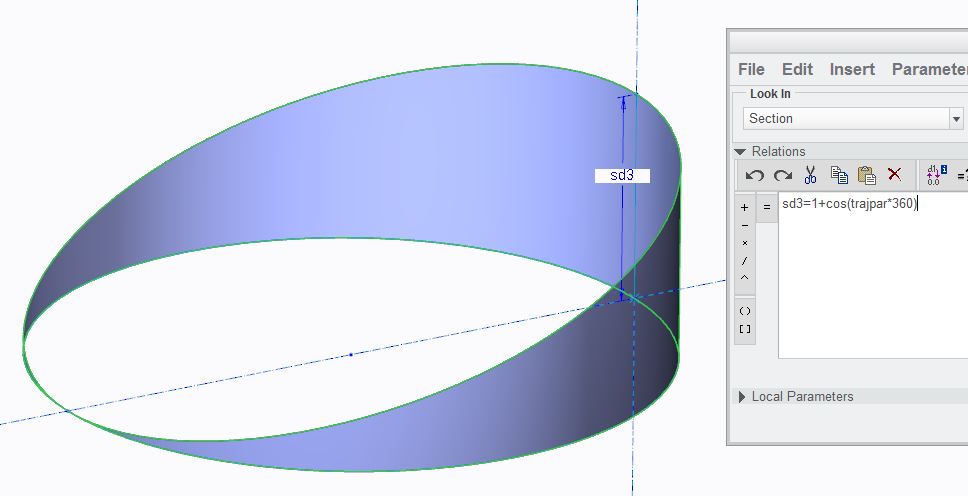
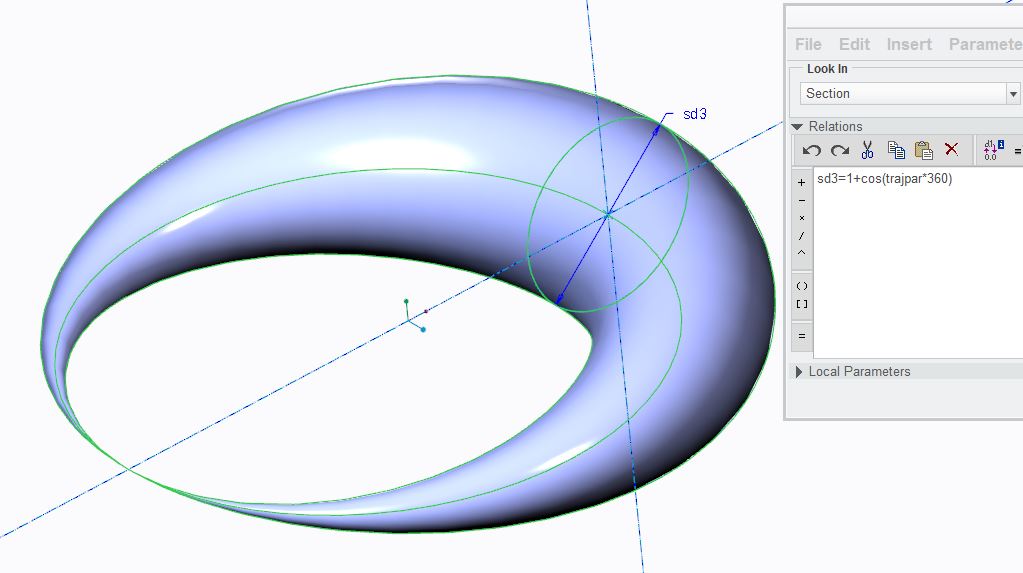
A circle with a variable diameter: As in the line above, the circle diameter is 2 to 0 to 2 again.
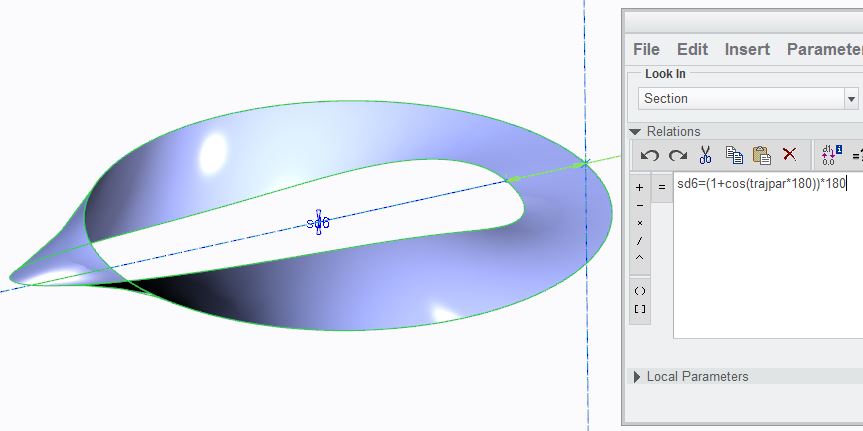
 Revolving a line along a closed trajectory is little more complex, apparently. The reason for this is not immediately apparent. In this case, the value range is 1 to -1 and not back to 1 (half the cosine wave). Also, the full range -must- convert to "360" or multiples there-of. The same "1+..." statement is to convert the value range from 2 to 0 (all positive or zero). The "...*180" makes the value range 0 to 360. But also notice the "cos(trajpar*180)". In this instance, we only want one direction of rotation from 360 to 0. This is the special condition where 360=0 and therefore abides by the basic rule #1; the end condition must be the same as the beginning. Any other value in this statement that does not result in a value following rule #1 -will- fail. However, this particular closed loop with a revolving section does not require a sine function. In fact, you can revolve the line linearly using "d(n)=trajpar*360". Again, for the very reason that this range of 0 degrees to 360 degrees create the same end condition as the start condition. Try replacing "...360" with "d(n)=trajpar*(360*20)" in the Relation for multiple loops around the trajectory path similar to the next example.
 of course, these are simplified examples but the power of these equations should be self-evident. The following examples show that angles with values greater than 360 are allowed: sd9=trajpar*720...
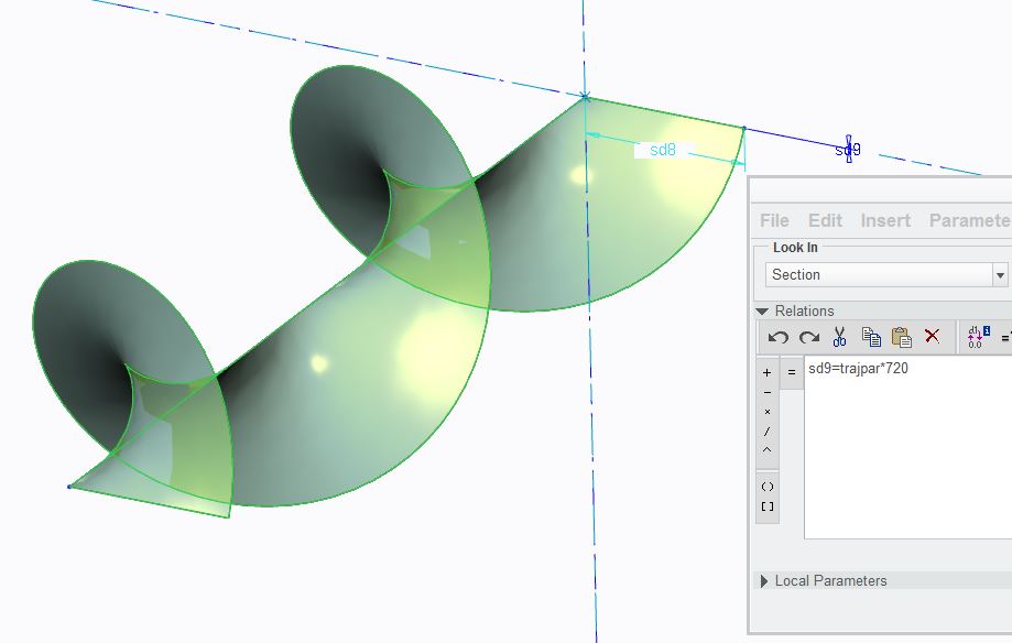
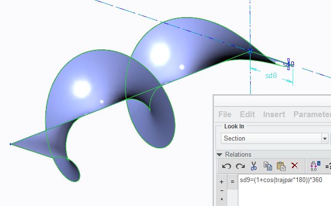
In this instance, the open trajectory uses "trajpar" directly using the value 0 to 1. sd9 is an angle dimension where at the start of the trajectory "0*720=0" and at the end, "1*720=720". This creates 2 full rotations of the line defined by sd8. Now see what happens is you replace this with a curve function by replacing the sd9 statement with "sd9=(1+cos(trajpar*180))*360". Notice how the ends are now beautifully tangent to a horizontal plane.
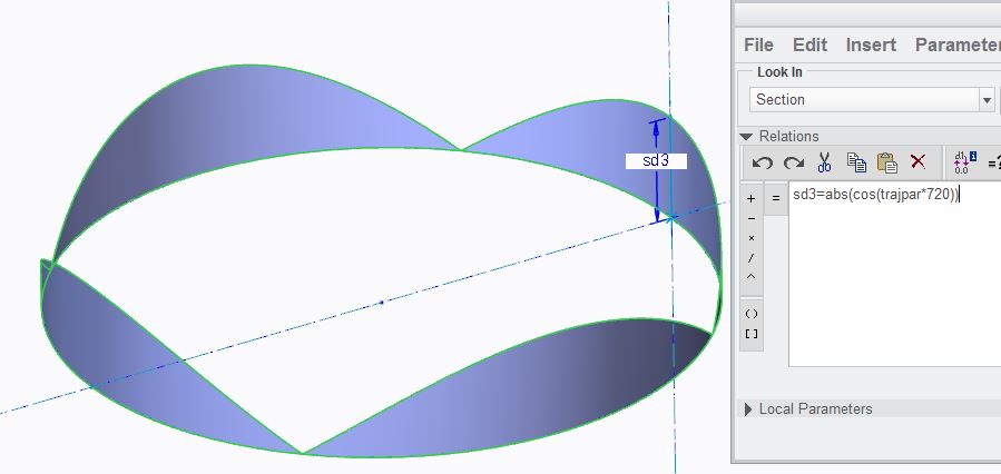
There are endless solutions that can create some very specialized section geometry, not to mention the multitude of applicable trajectories. Here is another way to remove the "-1" aspect of the sine wave. In the case - sd3=abs(cos(trajpar*720)) ...includes 2 cosine waves with all the negative values inversed with the abs() function. Again, zero is encountered 4 times.
Of course, none of this means anything if you followed the rules; you know there is no negative value in the equation; you know the ends of the closed trajectory have the same condition at the beginning as at the end; and you know that all trajpar statements were used in accordance with the rules, and it still fails. Next you have to look at what your sketch is doing at the various values. I cannot tell you the level of frustration I have with the Solver. Even static sketches can really test us, but when the sketch becomes dynamic, all manner of strange incarnations tend to occur, many of which could even crash your session. Fortunately, when you define a VSS, the system evaluates the sketch throughout the range of the trajpar variable before it "casts it in concrete". Even if the Relation statement passes mustard, that is no guarantee that the VSS Sweep will accept it. -If- you get a preview that looks like it has followed a variable section, you are in luck. You did something right!
Test you sections. Replace the variable with values that you know it will encounter. Suspend the Relation and drag the sketch to check it for robustness (lock the other dimensions 1st!). If nothing else, you will learn if your sketch is robust enough to handle the manipulation. I'm willing to put forth the statement that rotational aspects along a trajectory will be the least stable in any given sketch. It is my hope that the observations above will provide a better understanding of VSS and the trajpar variable do.
If you find this document useful, please remember to rate and like this.
Thanks, and may your VSS work for you.
This thread is inactive and closed by the PTC Community Management Team. If you would like to provide a reply and re-open this thread, please notify the moderator and reference the thread. You may also use "Start a topic" button to ask a new question. Please be sure to include what version of the PTC product you are using so another community member knowledgeable about your version may be able to assist.