
Turn on suggestions
Auto-suggest helps you quickly narrow down your search results by suggesting possible matches as you type.
Showing results for
Please log in to access translation
Turn on suggestions
Auto-suggest helps you quickly narrow down your search results by suggesting possible matches as you type.
Showing results for
Community Tip - You can subscribe to a forum, label or individual post and receive email notifications when someone posts a new topic or reply. Learn more! X
- Community
- Creo+ and Creo Parametric
- 3D Part & Assembly Design
- Re: Enforced displacement, tangential direction, m...
Translate the entire conversation x
Please log in to access translation
Options
- Subscribe to RSS Feed
- Mark Topic as New
- Mark Topic as Read
- Float this Topic for Current User
- Bookmark
- Subscribe
- Mute
- Printer Friendly Page
Enforced displacement, tangential direction, more than 1 revolution
Dec 08, 2015
08:01 AM
- Mark as New
- Bookmark
- Subscribe
- Mute
- Subscribe to RSS Feed
- Permalink
- Notify Moderator
Please log in to access translation
Dec 08, 2015
08:01 AM
Enforced displacement, tangential direction, more than 1 revolution
I've been doing some experimenting with large deformation analysis.
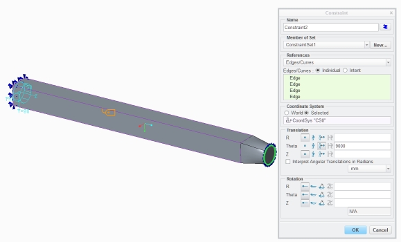
I want to twist the end of the beam around, several times (don't ask why, I just need it done).
In a large deformations analysis you can not prescribe a tangential displacement in radians. It has to be "unit of length" mm in my case. So I did this for the circular curve on the end of the tapered bit
I get it to rotate about 360 degrees, no further, however large I make the value for prescribed displacement (the value in the field is now 9000mm (160 full turns....).I stopped the analysis after I found out that displacements no longer increased.
Any body knows how to tackle this?
Shall we classify this as a bug?
This thread is inactive and closed by the PTC Community Management Team. If you would like to provide a reply and re-open this thread, please notify the moderator and reference the thread. You may also use "Start a topic" button to ask a new question. Please be sure to include what version of the PTC product you are using so another community member knowledgeable about your version may be able to assist.
Solved! Go to Solution.
Labels:
- Labels:
-
Assembly Design
ACCEPTED SOLUTION
Accepted Solutions
Dec 08, 2015
08:17 AM
- Mark as New
- Bookmark
- Subscribe
- Mute
- Subscribe to RSS Feed
- Permalink
- Notify Moderator
Please log in to access translation
Dec 08, 2015
08:17 AM
What about the "interpret angular translations in radians" check-box?
Could you attach your end face to a single point using a rigid link (or a weighted link and a spring), and apply a rotation to the point? You could try applying that rotation in a Cartesian csys to see whether that works any better...
13 REPLIES 13
Dec 08, 2015
08:17 AM
- Mark as New
- Bookmark
- Subscribe
- Mute
- Subscribe to RSS Feed
- Permalink
- Notify Moderator
Please log in to access translation
Dec 08, 2015
08:17 AM
What about the "interpret angular translations in radians" check-box?
Could you attach your end face to a single point using a rigid link (or a weighted link and a spring), and apply a rotation to the point? You could try applying that rotation in a Cartesian csys to see whether that works any better...
Dec 08, 2015
08:33 AM
- Mark as New
- Bookmark
- Subscribe
- Mute
- Subscribe to RSS Feed
- Permalink
- Notify Moderator
Please log in to access translation
Dec 08, 2015
08:33 AM
Jonathan:
The interpret etc. is not allowed for large displacements, this is definitely large displacements, So I can not use the check box.
I'll try with the point and the link(s) as soon as my regular analysis completes, but I fear.......
Well let's not get ahead of that.
I'll keep you informed on the developments.
Erik
Dec 09, 2015
05:05 AM
- Mark as New
- Bookmark
- Subscribe
- Mute
- Subscribe to RSS Feed
- Permalink
- Notify Moderator
Please log in to access translation
Dec 09, 2015
05:05 AM
I tried to circumvene te problem by applying a load instead of a displacement.
Unfortunately I seem to be running into the same limitation: the model runs fine up to 360 degrees, but does not want to go beyond 360 degrees rotation.
Declaring it a bug sounds like a good idea, let's hear why this is such an impossibility. If PTC wants to go nonlinear they should do it right.
Dec 09, 2015
05:11 AM
- Mark as New
- Bookmark
- Subscribe
- Mute
- Subscribe to RSS Feed
- Permalink
- Notify Moderator
Please log in to access translation
Dec 09, 2015
05:11 AM
Jonathan
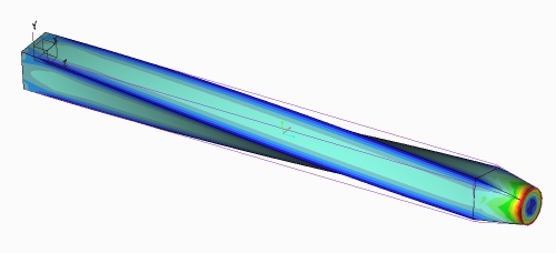
Rigid link and prescribed rotation around z-axis on the free point worked. looks great, Thank you!
Will look into the instabilities, but this is 600 degrees of rotation.
Dec 09, 2015
05:15 AM
- Mark as New
- Bookmark
- Subscribe
- Mute
- Subscribe to RSS Feed
- Permalink
- Notify Moderator
Please log in to access translation
Dec 09, 2015
05:15 AM
it's done Patrick, I need the rigid link. Fun is, that if you continue after the 600 degrees, you get the next shape, as you would when wring a towel. Looks ugly, would need refinement to do it right is not of intrest now.
Summary: Large displacements go a long way in simulate
(PTC: I will claim that statement for my own marketing  )
)
Dec 09, 2015
05:32 AM
- Mark as New
- Bookmark
- Subscribe
- Mute
- Subscribe to RSS Feed
- Permalink
- Notify Moderator
Please log in to access translation
Dec 09, 2015
05:32 AM
If it is technically feasible for the solver, there is all the more reason to declare it a bug!
Dec 09, 2015
05:42 AM
- Mark as New
- Bookmark
- Subscribe
- Mute
- Subscribe to RSS Feed
- Permalink
- Notify Moderator
Please log in to access translation
Dec 09, 2015
05:42 AM
I'm not that convinced that declaring it a bug will bring me anything, please look at:
Non-symmetric results for symmetric model and load?
Close to 10 months ago, no solution yet. An absolute disgrace.
I prefer a workaround such as Jonathan provided.
Erik
Dec 09, 2015
06:38 AM
- Mark as New
- Bookmark
- Subscribe
- Mute
- Subscribe to RSS Feed
- Permalink
- Notify Moderator
Please log in to access translation
Dec 09, 2015
06:38 AM
Laziness! 
If you don't report it, you can be sure that it will not improve, and you will be stuck using workarounds for ever and ever.
If you want the software to improve, you should actively chase after PTC. But yes, the 'return on investment' may be disappointingly (s)low.
Dec 09, 2015
08:29 AM
- Mark as New
- Bookmark
- Subscribe
- Mute
- Subscribe to RSS Feed
- Permalink
- Notify Moderator
Please log in to access translation
Dec 09, 2015
08:29 AM
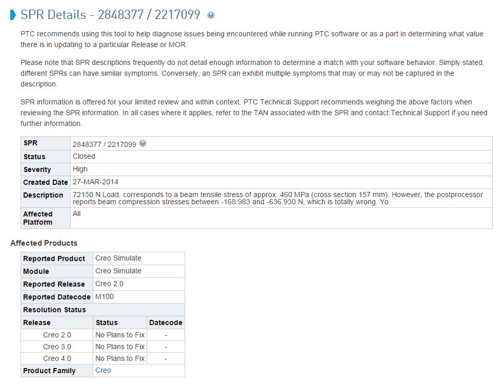
I found an SPR some time ago, for a bug that cost me 2 days of searching for modeling errors. PTC's plan for this particular bug looks like this:
Creo 2.0 No plan to fix
Creo 3.0 No plan to fix
Creo 4.0 No plan to fix

Dec 28, 2015
09:13 PM
- Mark as New
- Bookmark
- Subscribe
- Mute
- Subscribe to RSS Feed
- Permalink
- Notify Moderator
Please log in to access translation
Dec 28, 2015
09:13 PM
I'm somewhat not surprised. The quality of Simulate has seemed to take a hit ever since PTC shutdown the San Jose office (which housed the original creators of Mechanica that were still with the company) and shifted their responsibilities to India.
Dec 29, 2015
12:22 AM
- Mark as New
- Bookmark
- Subscribe
- Mute
- Subscribe to RSS Feed
- Permalink
- Notify Moderator
Please log in to access translation
Dec 29, 2015
12:22 AM
Hi Shaun and all,
Thank you for your post and I appreciate your feedback. Comments like this are not taken lightly and I am looking into both issues referenced in the above thread (SPR 2848377 and SPR 2873817).
At PTC we have strict policies in place in order to deliver a high quality product to our users. Please allow me time to review the two issues and discuss with development. I will provide a response to this forum based on my findings.
Lastly, I would like to emphasize the importance of logging calls when you encounter such issues. This will help us reproduce, discover and solve the issue. In some cases, these calls help guide me into introducing new enhancements in future releases to broaden the product.
If you have any questions or would like to discuss this issue, I welcome your email at -.
Regards,
Mark Fischer
Director, Product Management
Jul 01, 2016
07:42 AM
- Mark as New
- Bookmark
- Subscribe
- Mute
- Subscribe to RSS Feed
- Permalink
- Notify Moderator
Please log in to access translation
Jul 01, 2016
07:42 AM
Mr. Fischer, what was the outcome of your investigation?
Jul 15, 2016
05:03 PM
- Mark as New
- Bookmark
- Subscribe
- Mute
- Subscribe to RSS Feed
- Permalink
- Notify Moderator
Please log in to access translation
Jul 15, 2016
05:03 PM
Hi all,
My apologize for take so long to provide an update.
I will try to break this down into three topics.......as there are three items covered in this thread.
1) Enforced displacement, tangential direction, more than 1 revolution
This was the initial topic and discussion in this thread. As described by Erik, to achieve the desired results you will need to create a rigid link and prescribed rotation around the given axis (in this case z-axis) on the free point to get it to work. This would be the easiest way to setup the model and have it perform correctly. Note: this issue did not have a Call/SPR assigned to it. If you feel this is still an issue, I kindly ask that you raise a TS call so it can be properly tracked and addressed.
2) SPR 2873817 - Unsymmetrical results for a rotational symmetric cone model and load
I have provided a detailed explanation and update on this issue in the following thread - Non-symmetric results for symmetric model and load?
3) SPR 2848377 - 72150 N Load, corresponds to a beam tensile stress of approx. 460 MPa (cross section 157 mm). However, the postprocessor reports beam compression stresses between -168.983 and -636.930 N, which is totally wrong.
We still believe this works to spec, as based on reviewing the users model the load 72150 N is a result of thermal shrink applied on beams and therefore its nature is compressive and not tensile. Now I have asked development to investigate this issue, but it is a lower priority compared to a number of other open issues from the same user. We will re-open and investigate this issue once we have submitted the other fixes.
Hope this helps.
Regards,
Mark


