
Turn on suggestions
Auto-suggest helps you quickly narrow down your search results by suggesting possible matches as you type.
Showing results for
Please log in to access translation
Turn on suggestions
Auto-suggest helps you quickly narrow down your search results by suggesting possible matches as you type.
Showing results for
Community Tip - New to the community? Learn how to post a question and get help from PTC and industry experts! X
- Community
- Creo+ and Creo Parametric
- 3D Part & Assembly Design
- Re: Equal Length Constraint in Assembly
Translate the entire conversation x
Please log in to access translation
Options
- Subscribe to RSS Feed
- Mark Topic as New
- Mark Topic as Read
- Float this Topic for Current User
- Bookmark
- Subscribe
- Mute
- Printer Friendly Page
Equal Length Constraint in Assembly
Jun 17, 2023
04:54 AM
- Mark as New
- Bookmark
- Subscribe
- Mute
- Subscribe to RSS Feed
- Permalink
- Notify Moderator
Please log in to access translation
Jun 17, 2023
04:54 AM
Equal Length Constraint in Assembly
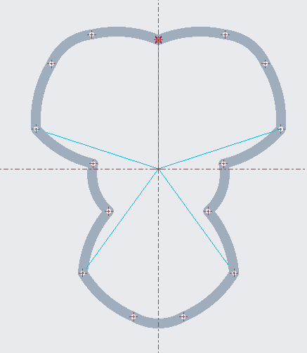
I would like to make these linkages move together, the easiest way to do this as I think is making the distance from the origin the same for the links (indicated by the lines drawn). However, I am unable to find a way to do that, any and all help would be greatly appreciated.
*I am using PTC creo parametric 9.0 student edition
Solved! Go to Solution.
Labels:
- Labels:
-
Assembly Design
ACCEPTED SOLUTION
Accepted Solutions
Jun 17, 2023
05:36 AM
- Mark as New
- Bookmark
- Subscribe
- Mute
- Subscribe to RSS Feed
- Permalink
- Notify Moderator
Please log in to access translation
15 REPLIES 15
Jun 17, 2023
05:36 AM
- Mark as New
- Bookmark
- Subscribe
- Mute
- Subscribe to RSS Feed
- Permalink
- Notify Moderator
Please log in to access translation
Jun 17, 2023
08:07 AM
- Mark as New
- Bookmark
- Subscribe
- Mute
- Subscribe to RSS Feed
- Permalink
- Notify Moderator
Please log in to access translation
Jun 17, 2023
08:07 AM
Thanks for the reply but I am not sure how to constrain the sketch to the links in assembly, I would appreciate it if you could guide me further.
Jun 17, 2023
08:28 AM
- Mark as New
- Bookmark
- Subscribe
- Mute
- Subscribe to RSS Feed
- Permalink
- Notify Moderator
Please log in to access translation
Jun 17, 2023
08:28 AM
After working around with this, this actually works perfectly fine, thank you for the help.
I currently have the sketch placed like this in the model tree so I can define the subassemblies and parts based on the sketch, however this means I cannot use "drags components" anymore since they are not free to move, do you have any tips regarding that?
Much thanks,
Ibrahim
Jun 17, 2023
08:56 AM
- Mark as New
- Bookmark
- Subscribe
- Mute
- Subscribe to RSS Feed
- Permalink
- Notify Moderator
Please log in to access translation
Jun 17, 2023
08:56 AM
Hi,
I do not understand why do you want to drag components. Draging is available when assembly components are assembled using mechanism constraints.
Please explain how do you want to move components - show it using picture with arrows.
Q: Modification of sketch dimension is not enough?
Martin Hanák
Jun 17, 2023
09:29 AM
- Mark as New
- Bookmark
- Subscribe
- Mute
- Subscribe to RSS Feed
- Permalink
- Notify Moderator
Please log in to access translation
Jun 17, 2023
09:29 AM
The assembly is connected via Pin Connections at the "holes" (image attached), I have attached two images where I change the sketch dimensions and the result (which are perfectly fine). I am wondering if there is a method to drag the components to achieve the same result.
I am a university student trying to learn creo, modifying sketch is definitely an acceptable solution to what I asked, it is just out of curiosity I am asking if dragging components can be used.
Jun 17, 2023
11:16 AM
- Mark as New
- Bookmark
- Subscribe
- Mute
- Subscribe to RSS Feed
- Permalink
- Notify Moderator
Please log in to access translation
Jun 17, 2023
11:16 AM
I am attaching a picture of what I had hoped to and have achieve successfully geometry wise. Many thanks to Martin.
Jun 18, 2023
08:40 AM
- Mark as New
- Bookmark
- Subscribe
- Mute
- Subscribe to RSS Feed
- Permalink
- Notify Moderator
Please log in to access translation
Jun 18, 2023
08:40 AM
@IT_10439331 wrote:
The assembly is connected via Pin Connections at the "holes" (image attached), I have attached two images where I change the sketch dimensions and the result (which are perfectly fine). I am wondering if there is a method to drag the components to achieve the same result.
I am a university student trying to learn creo, modifying sketch is definitely an acceptable solution to what I asked, it is just out of curiosity I am asking if dragging components can be used.
Hi,
I am not expert in case of mechanisms ... therefore I do not know if dragging components can be used.
However, after a bit of searching, I figured that your model would have to come up with connections between components.
An example of connection is shown in https://www.youtube.com/watch?v=Vmihj3Il0UY video.
Also I downloaded runner.zip from https://community.ptc.com/t5/3D-Part-Assembly-Design/Simultaneous-Mechanism-Motion/m-p/147567#M11399 discussion ... see uploaded video.
Martin Hanák

If you enjoy my content, please consider supporting what I do: Buy a Coffee for 4KSide - https://ko-fi.com/J3J6B8N0 or DONATE by https://www.paypal.me/4kside WHY SHOULD YOU DONATE TO 4K SIDE? More donation = more money More money allows me to buy more coffee More coffee makes me create more Creo ...
Jun 19, 2023
09:26 AM
- Mark as New
- Bookmark
- Subscribe
- Mute
- Subscribe to RSS Feed
- Permalink
- Notify Moderator
Please log in to access translation
Jun 19, 2023
09:26 AM
Hi,
I think you can use Cam-Follower connection to move 5 "points" simultaneously by rotating shaft with 5 cams.
https://www.youtube.com/watch?v=tfob1bF6Pxg
Martin Hanák

If you enjoy my content, please consider supporting what I do: Buy a Coffee for 4KSide - https://ko-fi.com/vpalffy or DONATE by https://www.paypal.me/4kside WHY SHOULD YOU DONATE TO 4K SIDE? More donation = more money More money allows me to buy more coffee More coffee makes me create more Creo ...
Jun 19, 2023
12:21 PM
- Mark as New
- Bookmark
- Subscribe
- Mute
- Subscribe to RSS Feed
- Permalink
- Notify Moderator
Please log in to access translation
Jun 19, 2023
01:08 PM
- Mark as New
- Bookmark
- Subscribe
- Mute
- Subscribe to RSS Feed
- Permalink
- Notify Moderator
Please log in to access translation
Jun 19, 2023
01:08 PM
I had a realisation that the length can be maintained by using constraints on the angles in the geometry. I started this sketch and it helped me a lot (Sketch image below), I realised the chord would be an isoceles triangle with angles highlighted being 54 degrees regardless of length. So I made planes defined on the part at 54 degrees from the 0 degree (planes image below), by constraining the that plane to the corresponding previously placed piece's plane I can ensure they move in tandem (planes constrained image below).
I am also attaching a video of it working and the constraints used for posterity (constraint video below), I realise the menu has not been recorded, hopefully, the highlighted planes are enough to understand what is going on.
Martin you were a tremendous help, your replies motivated me to delve more into the forum and think deeply on the ways this could be achieved, I also really appreciate your help (for example downloading the runner file for example and uploading it working since I cannot directly access the file with the education version), I am blown away by your kindness and thoughtfulness. Thank you very much for your help
Jun 19, 2023
01:24 PM
- Mark as New
- Bookmark
- Subscribe
- Mute
- Subscribe to RSS Feed
- Permalink
- Notify Moderator
Please log in to access translation
Jun 19, 2023
01:24 PM
I am attaching my assembly for posterity, hopefully it can be of help to someone.
Jun 19, 2023
01:29 PM
- Mark as New
- Bookmark
- Subscribe
- Mute
- Subscribe to RSS Feed
- Permalink
- Notify Moderator
Please log in to access translation
Jun 19, 2023
01:29 PM
That is very interesting, I was meaning to get into trying out cams and followers, this is a perfect opportunity to dive into it, thank you very much.
Jun 20, 2023
04:49 AM
- Mark as New
- Bookmark
- Subscribe
- Mute
- Subscribe to RSS Feed
- Permalink
- Notify Moderator
Please log in to access translation
Jun 20, 2023
04:49 AM
I thought you might be interested in knowing what it all ended up as, I have attached a video. I used a cam connection on the hanging out bit ( i am not sure what to call it) and the wedge. The cam is supposed to be a conical cylinder, I am working on changing it.
Best,
Ibrahim
Jun 20, 2023
05:02 AM
- Mark as New
- Bookmark
- Subscribe
- Mute
- Subscribe to RSS Feed
- Permalink
- Notify Moderator
Please log in to access translation
Jun 20, 2023
05:02 AM
Hi,
it seems to me that it is better to add video as attachment instead of embedding it.
Martin Hanák
Jun 20, 2023
06:40 AM
- Mark as New
- Bookmark
- Subscribe
- Mute
- Subscribe to RSS Feed
- Permalink
- Notify Moderator
Please log in to access translation
Jun 20, 2023
06:40 AM
I apologise for the hassle you are right. The constraint video shows the constraints and the initial assembly. The video named complete shows well the almost completed assembly


