Community Tip - Have a PTC product question you need answered fast? Chances are someone has asked it before. Learn about the community search. X
- Community
- Creo+ and Creo Parametric
- 3D Part & Assembly Design
- Re: Excerpt from the PTC Technical Specialists E-N...
- Subscribe to RSS Feed
- Mark Topic as New
- Mark Topic as Read
- Float this Topic for Current User
- Bookmark
- Subscribe
- Mute
- Printer Friendly Page
Excerpt from the PTC Technical Specialists E-Newsletter July 2010 Edition
- Mark as New
- Bookmark
- Subscribe
- Mute
- Subscribe to RSS Feed
- Permalink
- Notify Moderator
Excerpt from the PTC Technical Specialists E-Newsletter July 2010 Edition
You can download the complete newsletter authored by Todd Kraft, by clicking here.
PTC Product Focus: What’s New in Pro/ENGINEER Mechanica for Wildfire 5.0
Tip of the Month: Creating Shell Elements in Wildfire 5.0
| PTC Product Focus |
| What’s New in Pro/ENGINEER Mechanica for Wildfire 5.0 |
|---|
Pro/ENGINEER Mechanica for Wildfire 5.0 is another significant release packed with new functionality and usability enhancements. You’ll find in this article some incredible new features that are going to make your experience with Mechanica easier and more powerful than before.
The What’s New in Pro/ENGINEER Mechanica can be broken down into five categories which will be used to describe the enhancements:
• Usability and Workflow
• New Modeling Tools and Features
• Weldment and Midsurface Modeling Enhancements
• Enhanced Solution Capability
• Post-processing and Results
The list that is in this document isn’t the full list of enhancements in Mechanica. This is a list of the top enhancements that will have the greatest impact on users in Wildfire 5.0.
Usability and Workflow
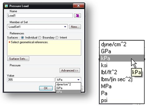
Support for Heterogeneous Units
The units for all modeling entities may be now set on the fly. There is also a built in conversion tool for converting from one unit to another. You can also see results in any type of units you wish to. This enhancement makes life much easier.
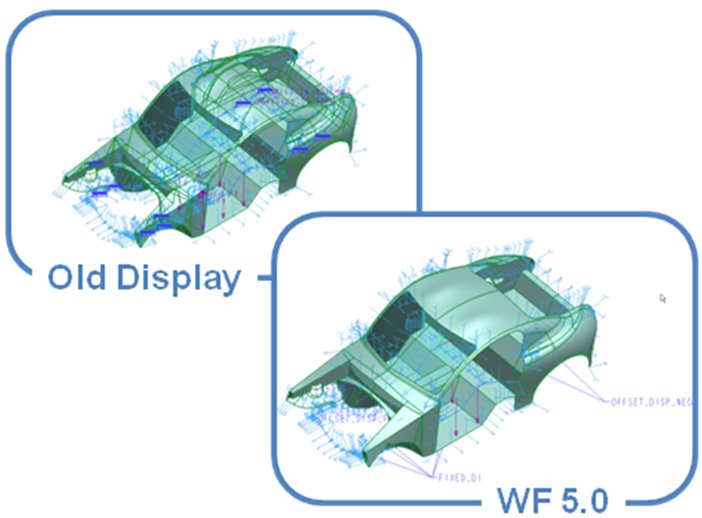
Icon and Label Display Improvements
We’ve added a z-buffering capability to Mechanica for display of icons that represent different aspects of the model setup. This greatly reduces visual clutter on the screen. You can also control the distribution density for different types of loads. In addition, you can now set colors individually and highlight referenced entities.
Dashboard UI for Surface and Volume Regions
We’ve now updated the dashboard UI for these two definitions. This includes a geometry preview, a simplified definition UI and some new options like ‘surface region split by chain’ and ‘volume region depth options.’
Smaller enhancements for Usability and Workflow
Here are additional enhancements around usability and workflow:
• Material limits consolidated and no longer coupled to specific failure criteria
• Persistent display of Csys triad
• Zoom into command available for any selected simulation entity
• New tabbed interface for displaying solution status files.
New Modeling Tools and Features
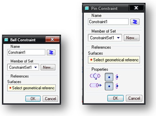
Pin, Ball and Planar Constraints
It is now easier to specify engineering constraints with these new features. They can be applied to any corresponding geometry.
Advanced Reference Selection
You now have the ability to use intent references and the ability to use datum reference features. This enables a user to ‘tag’ geometry for simulation entities without entering Mechanica. For example, add the internal surfaces of a valve body to a datum reference feature and in Mechanica apply a pressure load to the surfaces in this feature.
Here are additional enhancements new modeling tools and features:
• Total bearing load at a point
• Total volumetric heat load can be specified as a total load
• Reaction measures at a point
• Beam releases on curves
• Preview of imported loads
Weldment and Midsurface Modeling Enhancements
New Shell Pair Definition Workflow
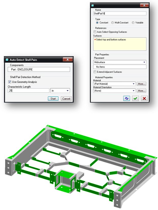
Wildfire 5.0 has an updated and streamlined UI and workflow for creating shell elements. You now have access to a quick repeat and automated selection of opposing surfaces. This includes a ‘geometry based’ shell pair auto-detection and not a modeling method detection like previous releases. In addition, the compression of pairs has a tangent surface option. This works for both assembly and part modes. You’ll find this functionality very useful you’ll be amazed how much time you’ll save.
What about my Pro/WELD information?
Now with Wildfire 5.0, you can reuse all your Pro/WELD work that you did in assembly mode. You simply select the Pro/E welds that you’d like to include and they are then added into your assembly as shell elements. You can also define separate material properties for the weld features.
Enhanced Solution Capability
Nonlinear Elasto-plastic Materials
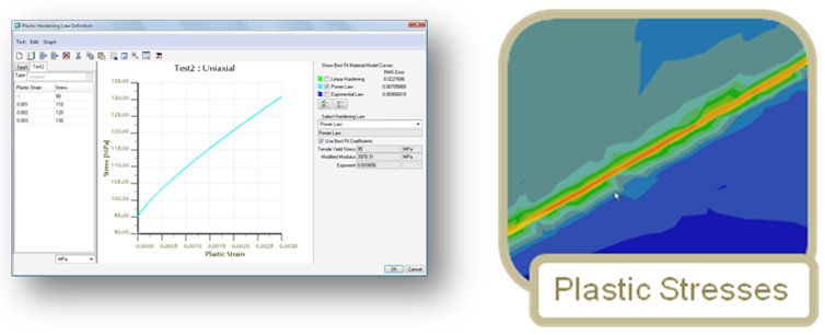
For the first time ever, Pro/MECHANICA has entered into the material plasticity world with new functionality in Wildfire 5.0! We can now support nonlinear elasto-plastic materials. The three most common material laws can be applied, which are linear hardening, power law and exponential law. The material definition window is very easy to use and has material fitting capability so that it selects the most appropriate material law or allows you to select the one you with to use. You can now understand the post-yield behavior and both loading and unloading are supported.
Greater Solution Accuracy with:
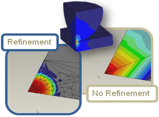
• New algorithm for mesh refinement in contact
• Convergence/Error Plots for Single Pass Adaptive (SPA)
• Convergence target selection for SPA
• Large deflection Analysis now supports rigid links
Post Processing and Results
Many additional capabilities for post processing:
• Principle stress vector results
• Relative paths for the .rwd file
• Beam thickness display control (adds much more realism to beam results
Mechanica results in PDMLink
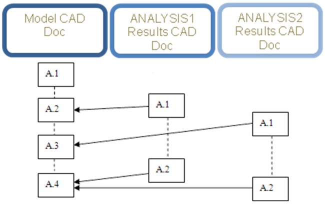
Both ‘raw’ study directories as well as HTML reports are supported in PDMLink. A new option has been added in Wildfire 5.0 in the RUN dialog box which enables you to ‘vault results.’ This creates a zip archive of the study directory and moves it to the workspace as a separate document. It references the last checked in version of the model as a derived link. You can browse to these files directly. The HTML reports are also auto associated to the model in session. The HTML report is saved to the workspace upon save. The following image helps you understand the link of the results with the corresponding files:
| Tip of the Month |
| Creating Shell Elements in Wildfire 5.0 |
|---|
This is one of the biggest time savers in all of Pro/ENGINEER Wildfire 5.0, if not the biggest! Creating shell elements manually has always been a tedious task when the geometry was imported or you were not able to auto pair most of an assembly. But the fact remained, you had to pair everything at the part level and could not do any of the work at the assembly level. Well, not anymore! You can do the entire assembly at the assembly level with just a few mouse clicks. And you can create these ‘geometry based’ pairs in either part or assembly level. Here is how this is done and how you can save yourself hours of work by creating shell elements in assembly mode!
Step 1 – Open the Assembly and enter Mechanica Mode
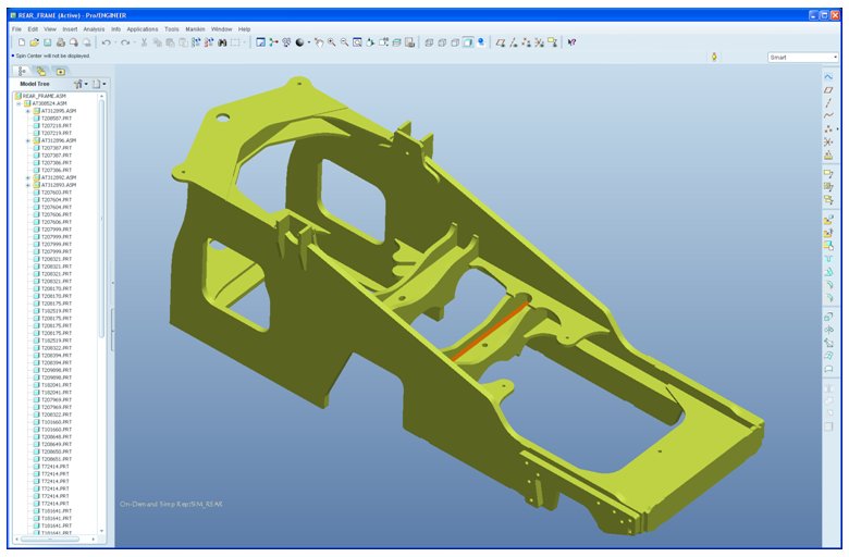
Open any assembly inside of Pro/ENGINEER. We’ll use this weldment as shown. After you open it, go into Mechanica by selecting APPLICATIONS>MECHANICA.
Step 2 – Create the shell pairs
You need to understand the thickness of the geometry that you are dealing with. Go ahead and make some measurements to understand the thickness of the plates or geometry that you are working with. This is simply done with the Analysis>Measure menu. Next thing to do right now is click on INSERT>MIDSURFACE>AUTO DETECT SHELL PAIRS. The following dialog box appears: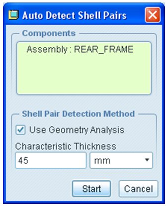
Select the top level assembly node or the assembly name that you want to mesh from the model tree. Enter the value of the thickness you’d like to pair geometry based on. Mechanica will now pair any geometry that is equal or less than this value. Then click START! In just a second, all your pairs are done! Really, they are complete! In this example, 34 shell pairs were created.
Step 3 – Review the shell pairs
Next, let’s see how we did! Select AUTOGEM>REVIEW GEOMETRY. This is a new dialog box in Wildfire 5.0.
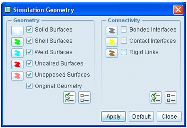
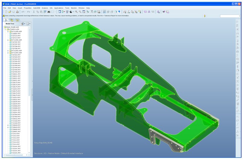
Make certain that ‘Shell Surfaces’ is selected. After you see this dialog box, select ‘APPLY’ to review your shell surfaces. You’ll be prompted that this may take a considerable amount of time, but just say OK to that dialog box. Now take a look at the shell surfaces – this is a huge time saver! After you’ve reviewed the shell pairs, close the REVIEW GEOMETRY dialog box.
Step 4 – Review the mesh
If you have material properties already applied to your assembly, then you can mesh your model. This step is just to verify that you have valid shell elements and to get an idea of how many elements you are dealing with when you solve your analysis later on. Click on the ‘Create Elements’ icon or select AUTOGEM>CREATE. Then click on the ‘Create’ button in the dialog box. After a few seconds, my assembly now looks like this:
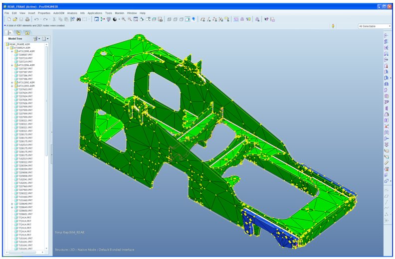
Wow, from start to finish, this is a 2 minute process. Compare this to the process in previous revisions where it would take a substantially more time to get this far.
I hope you enjoyed this tutorial and can apply it to your use of Mechanica!
You can download the complete newsletter authored by Todd Kraft, by clicking here.
This thread is inactive and closed by the PTC Community Management Team. If you would like to provide a reply and re-open this thread, please notify the moderator and reference the thread. You may also use "Start a topic" button to ask a new question. Please be sure to include what version of the PTC product you are using so another community member knowledgeable about your version may be able to assist.
- Mark as New
- Bookmark
- Subscribe
- Mute
- Subscribe to RSS Feed
- Permalink
- Notify Moderator
Hey John...
This is good stuff! Maybe instead of excerpting the newsletter 'as is', you could break it out and post it as separate items - as a way to keep it more pertinent? In any event, keep the quality of the content coming!
- Mark as New
- Bookmark
- Subscribe
- Mute
- Subscribe to RSS Feed
- Permalink
- Notify Moderator
Yes I had considered it before. It's worth me thinking about it again.
Thanks Alan for the feedback.


