Community Tip - You can subscribe to a forum, label or individual post and receive email notifications when someone posts a new topic or reply. Learn more! X
- Community
- Creo+ and Creo Parametric
- 3D Part & Assembly Design
- Exporting to OBJ with decent UV coords
- Subscribe to RSS Feed
- Mark Topic as New
- Mark Topic as Read
- Float this Topic for Current User
- Bookmark
- Subscribe
- Mute
- Printer Friendly Page
Exporting to OBJ with decent UV coords
- Mark as New
- Bookmark
- Subscribe
- Mute
- Subscribe to RSS Feed
- Permalink
- Notify Moderator
Exporting to OBJ with decent UV coords
UPDATE 2017-05-28: Bug NOT fixed in M130... my tests were flawed, and I jumped the gun. Double checked and behavior is still as was. HOWEVER - ptc support had told me M140, not M130. sorry. not fixed yet, but soonish ( est. Jul 26th for Creo 3.0 M140, and Sept 2017 for Creo 3.0 M030)
https://support.ptc.com/cs/product_calendar/PTC_Product_Calendar.htm
I started exporting to OBJ using planes for generating UV coords. However I have run into what appears to be a pretty substantial bug in the way the UVs are generated.
UV coordinates are necessary for texture mapping in other software. and sure you can usually re-map the UV coordinates in another piece of software, but that would mean that every time I export, I would have to re-process the file in a consistent way.
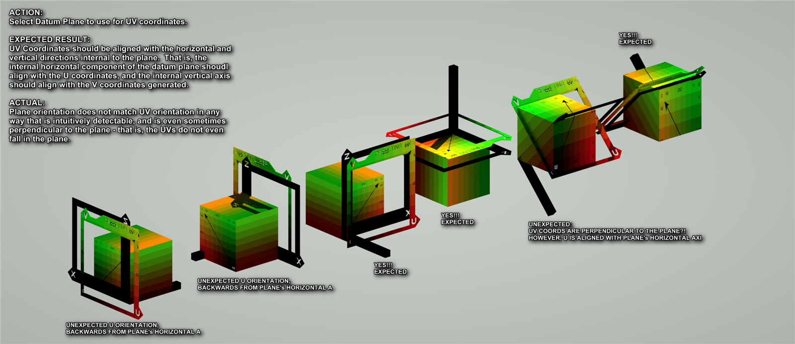
So, below is what I exported, and found really strange results.

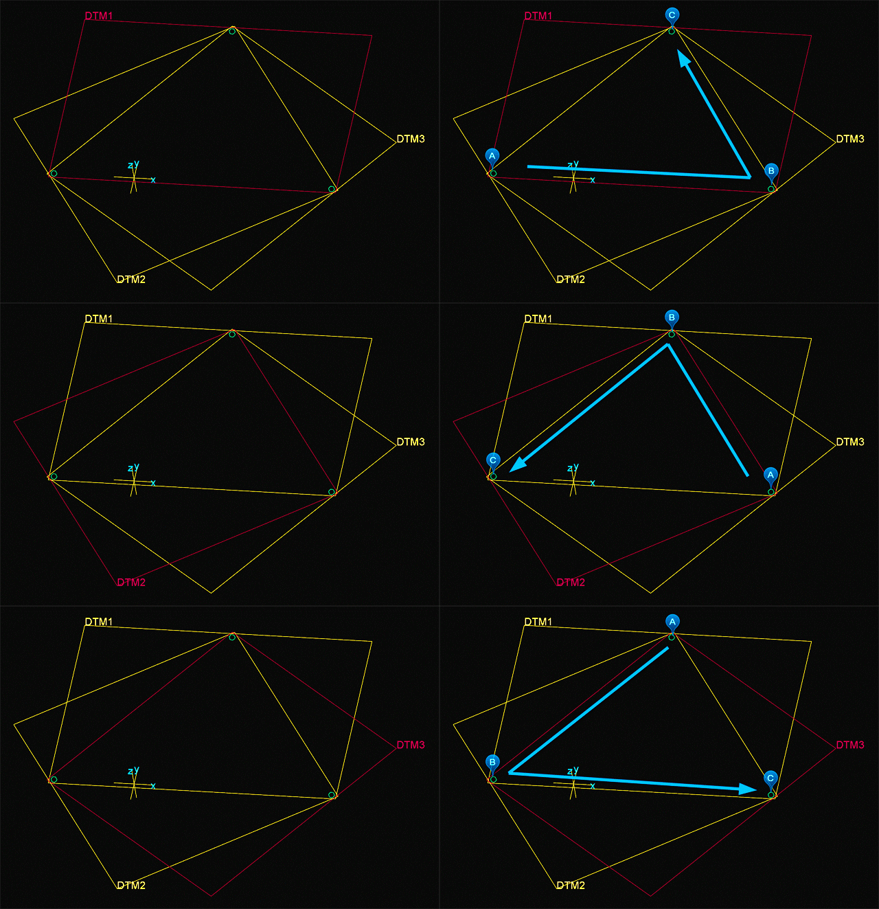
First off, you have to understand that Creo's datum planes internally have a horizontal (X-axis) and an internal vertical (z-axis) and a facing normal (y-axis) and even an origin - in other words, within a datum plane lives all the parts to define a coordinate system.
Below you see that 3 different datum planes can be created picking the 3 points in CCW order but starting from different point each time. if you pick in the CW order the plane normal will face the opposite direction A->B defines the X or horizontal. Then point C will lie in the positive vertical direction.

So when you pick a datum plane to define UV coordinates, one would expect the UV coordinates align with Horizontal and Vertical components of the plane and be aligned in the same orientation.
The test I did above found this is just not what's happening, but it's so unpredictable that I have spent a bit of time testing and building an illustrative model to explain what the UVs were doing to both me and to tech support.
My suspicion is that there is a matrix transformation that the export goes through and who's components are out of order or missing a row/column or something.
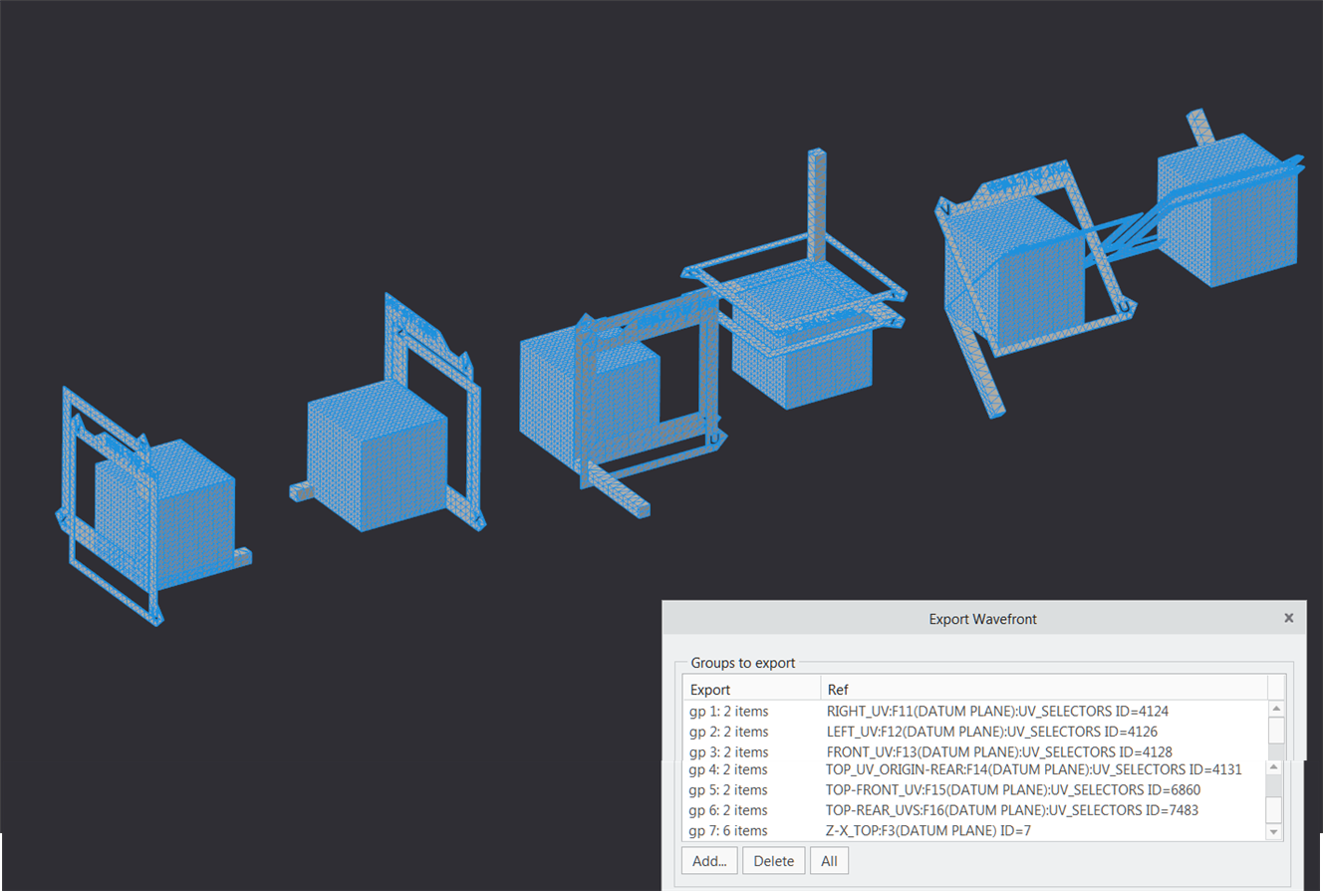
THIS is how one would replicate the UV coordinates generated above using the attached CREO assembly. PLEASE NOTE THE UVs for the assembly are not "automatically generated" you have to pick the object, click OK, then select the correct plane. I have attached the output OBJ that is shown in the rendering above using the UVs generated as shown below.

NOTE: PTC has a fix for this that is supposed to be included in an upcoming date-code. once I have the fix, I'll mark this as answered.
- Labels:
-
2D Drawing


