
Turn on suggestions
Auto-suggest helps you quickly narrow down your search results by suggesting possible matches as you type.
Showing results for
Please log in to access translation
Turn on suggestions
Auto-suggest helps you quickly narrow down your search results by suggesting possible matches as you type.
Showing results for
Community Tip - Did you get an answer that solved your problem? Please mark it as an Accepted Solution so others with the same problem can find the answer easily. X
- Community
- Creo+ and Creo Parametric
- 3D Part & Assembly Design
- FEM analysis of a spring
Translate the entire conversation x
Please log in to access translation
Options
- Subscribe to RSS Feed
- Mark Topic as New
- Mark Topic as Read
- Float this Topic for Current User
- Bookmark
- Subscribe
- Mute
- Printer Friendly Page
FEM analysis of a spring
Jun 05, 2015
04:21 AM
- Mark as New
- Bookmark
- Subscribe
- Mute
- Subscribe to RSS Feed
- Permalink
- Notify Moderator
Please log in to access translation
Jun 05, 2015
04:21 AM
FEM analysis of a spring
Hi all,
after months I have retaken in hand the analysis of a spring with the FEM.
Now at work we have introduced the Creo 3 for fem analysis, so I've used this.
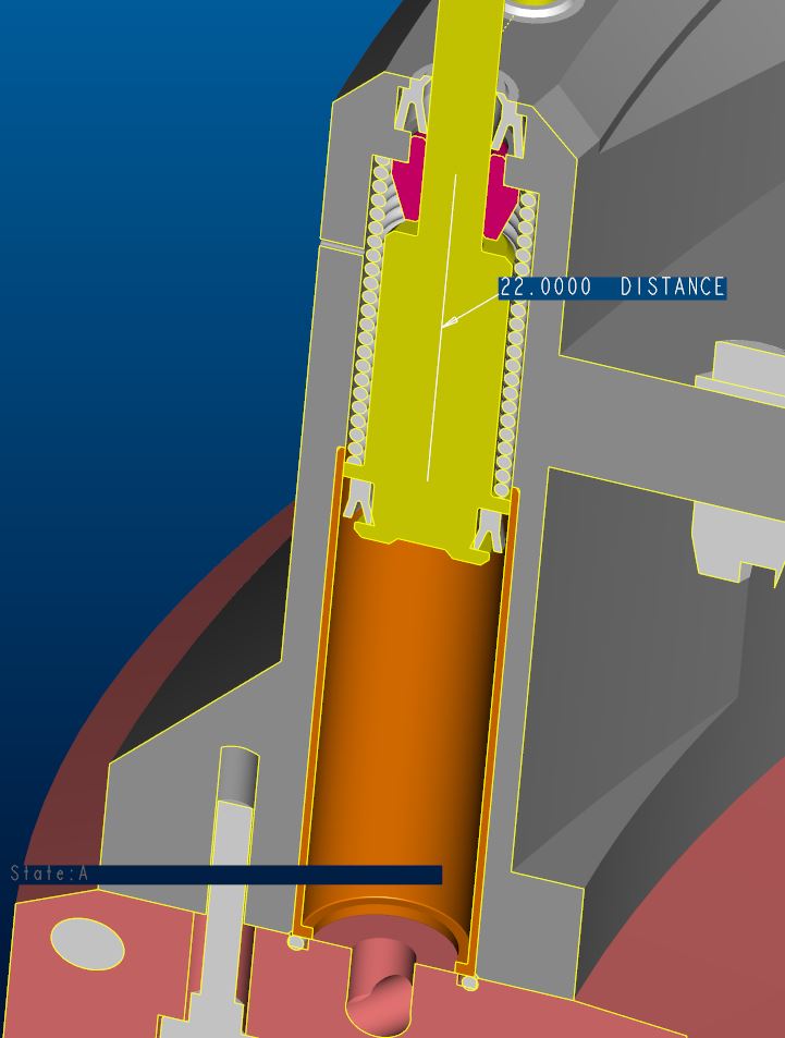
The free length of the spring is 76.55 mm; it works almost all compressed, 22 mm, and goes at 51 mm when it don't work, remaining preloaded.
For my analysis I just want see, in the first instance, what happen imposing not a force but a displacement of 10-20-40mm.
Is there something wrong in my analysis?
I've also used a elasto-plastic material but I think is not correct becouse a spring should work always in elastic mode.
I've insert also two contact surface because I had a compenetration of material, but in this manner tha analysis fails.
thanks for help.
Regards.
Labels:
- Labels:
-
Surfacing
15 REPLIES 15
Jun 05, 2015
07:37 AM
- Mark as New
- Bookmark
- Subscribe
- Mute
- Subscribe to RSS Feed
- Permalink
- Notify Moderator
Please log in to access translation
Jun 05, 2015
07:37 AM
A lot of questions spring to mind:
- why are you doing FEA on a spring? will you be manufacturing it yourself? usually you buy it, and the manufacturer will tell you exactly what the spring can handle
- why are you compressing the spring so much? this is usually a bad idea, it causes high stress in the spring, possibly even deformation, and you risk contact between the coils, causing surface damage, which causes fatigue crack initiation points. You seem to be using stainless steel, so without lubricant any rubbing contact will surely end in disaster.
- why do you want to use material plasticity? usually springs are meant to operate purely in the elastic range
As for your analysis: it seems to run well so far, except it takes a long time. After a few hours I'm now at step 11 / 30.
Seems to be setup properly. Large deformations is activated, My only comment would be that you now fully contrain the flat end surfaces of the spring, whereas in reality the situation may be different. Especially if your surfaces are not flat anymore when compressing the spring (but I don't know if that is the case).
Of course I haven't seen the results yet, so no comments there.
Jun 05, 2015
08:19 AM
- Mark as New
- Bookmark
- Subscribe
- Mute
- Subscribe to RSS Feed
- Permalink
- Notify Moderator
Please log in to access translation
Jun 05, 2015
08:19 AM
- It was only an excercise to see if I was able to simulate the springs with fem.
- The smallest length of the spring is 20.2 mm and the tensions are under the yield strength: in fact the spring is realized since a year and a half and it works well.
I designed it with tha formulas in the Shigley. - Using a material with no plasticity the program doesn't give right results if the deformations are big ang the yield strength is passed. The program told me that this limit was passed so I use a material like this; this thing sounded wrong. However if yield strength is not passed it works well in the same manner in linearity also with a elasto-plastic material.
With 40 mm of imposed displacement, my run fails around the 12th step.
Anyway it would be better rephrase the question in:
"If in the insane case you want to simulate a simple elical spring with FEM, what would be the right way to do this?"
Jun 05, 2015
08:50 AM
- Mark as New
- Bookmark
- Subscribe
- Mute
- Subscribe to RSS Feed
- Permalink
- Notify Moderator
Please log in to access translation
Jun 05, 2015
08:50 AM
Giulio,
I can't see that there's anything wrong with your model, principally speaking. But when you do nonlinear analysis with several effects at the same time, such as here with contact, large deformations, plasticity, then the solver may sometimes have difficulties converging. I would typically introduce nonlinear effects into the model one by one. Start for example with LDA only, and ignore contacts. I would also start by running the analysis as a quick check (P-level 3, one pass). This is in fact a strategy if you have difficulties converging in pass 2, refine the mesh and run the model as "quick check". You will get P-level of 3 which is better than most conventional FE-softwares. With a fine mesh you may get sufficiently accurate results. Perhaps try some mesh controls to get more brick/wedge elements may helt reaching convergence. Nonlinear analyses are more sensitive to mesh quality.
Nonlinear analyses are generally less accurate, since there are more physical penomenae included in the analysis. It is more important to capture what's going on on a more general level. So if accurate convergence for stress for every location in the model is not too important, then a refined mesh+quick check is often good enough in non-linear analysis.
I have ran your analysis now to almost 50% of max displacment (without plasticity & contact), but I need to leave to pick up kids at daycare.... have a good weekend.
/Mats L/
Jun 08, 2015
10:11 AM
- Mark as New
- Bookmark
- Subscribe
- Mute
- Subscribe to RSS Feed
- Permalink
- Notify Moderator
Please log in to access translation
Jun 08, 2015
10:11 AM
My run made it all the way through pass1, then made a local mesh refinement, then failed at time step 4 of pass 1.
It may help to create your own mesh refinement near the contact.
But like Mats said: large displacements, contacts, and material plasticity all combined in one model, is difficult to solve. (Even with a big tool like Abaqus, this is difficult to do).
Jun 09, 2015
03:11 AM
- Mark as New
- Bookmark
- Subscribe
- Mute
- Subscribe to RSS Feed
- Permalink
- Notify Moderator
Please log in to access translation
Jun 09, 2015
03:11 AM
I've done as Mats suggested and it works. But, although the analysis goes well, in the sense it goes to the end, there is a trouble: since the area where I put the "displacement load" is not symmetric, the spring bends sideways.
How can I simulate the real/good movement of the spring?
Jun 09, 2015
03:33 AM
- Mark as New
- Bookmark
- Subscribe
- Mute
- Subscribe to RSS Feed
- Permalink
- Notify Moderator
Please log in to access translation
Jun 09, 2015
03:33 AM
Giulio,
If you introduce the contacts near the ends of the springs, the deformation might become more symmetric. But as mentioned, it is more difficult to get a nonlinear analysis to converge, as the problem becomes more complex. The mesh becomes more important, for example. One strategy is to run the analysis as a "Quick check" (P-level 3 only) with a fine mesh.
And a possible explanation why the spring does not deform symmetrically, is simply that it does so also in reality.
/Mats
Jun 09, 2015
06:52 AM
- Mark as New
- Bookmark
- Subscribe
- Mute
- Subscribe to RSS Feed
- Permalink
- Notify Moderator
Please log in to access translation
Jun 09, 2015
06:52 AM
I've done as you said.
I've refined the mesh, removed the plasticity, done the quick check.
Jun 09, 2015
06:57 AM
- Mark as New
- Bookmark
- Subscribe
- Mute
- Subscribe to RSS Feed
- Permalink
- Notify Moderator
Please log in to access translation
Jun 09, 2015
06:57 AM
Cool animation! It looks as if the spring's contact with itself would prevent this bending of the spring, at least to some degree. So this would be the next step I think... I'm not sure Creo Simulate can handle surface contact "with itself". If so, then volume regions might help.
Jun 09, 2015
06:24 AM
- Mark as New
- Bookmark
- Subscribe
- Mute
- Subscribe to RSS Feed
- Permalink
- Notify Moderator
Please log in to access translation
Jun 09, 2015
06:24 AM
Hello
Attached is a document that can advise you.
It is in french but the drawings and formulas are "understandable language" fortunately.
This is may be not quite your case but the sentence of /Mats is just:
And a possible explanation why the spring does not deform symmetrically, is simply that it does so also in reality.
Kind regards.
Denis.
Jun 11, 2015
02:39 AM
- Mark as New
- Bookmark
- Subscribe
- Mute
- Subscribe to RSS Feed
- Permalink
- Notify Moderator
Please log in to access translation
Jun 11, 2015
02:39 AM
Hi Denis.
I've looked the file you have attached: there are the standard formulas for the springs.
In the chapter named "Flambage" it discussed the buckling of the spring and gives the coefficient from the elasticity theory.
Relatively of mine last update two threads behind, in the model we have instability because the load is applied not in the center, on the axis.
In which manner can I work around this issue?
Jul 03, 2015
02:34 AM
- Mark as New
- Bookmark
- Subscribe
- Mute
- Subscribe to RSS Feed
- Permalink
- Notify Moderator
Please log in to access translation
Jul 03, 2015
02:34 AM
Nobody can resolve this issue?
I understand that it is about a semi-theoretical problem, something that you can treat with classic formulas, but I think it is still interesting.
Jul 03, 2015
04:45 AM
- Mark as New
- Bookmark
- Subscribe
- Mute
- Subscribe to RSS Feed
- Permalink
- Notify Moderator
Please log in to access translation
Jul 03, 2015
04:45 AM
Hello
I do not know if this document in English can help you.
Kind regards.
Denis
https://webfiles.uci.edu/dbeerer/lit/Mechanical%20Springs%20Wahl.pdf
Jul 06, 2015
08:38 AM
- Mark as New
- Bookmark
- Subscribe
- Mute
- Subscribe to RSS Feed
- Permalink
- Notify Moderator
Please log in to access translation
Jul 06, 2015
08:38 AM
You should not design a spring to go all the way to it's solid height.
Most spring design is done by home grown math worksheets or by commercial packages such as:
Spring Manufacturers Institute Software
Also there is a very good plug in for ProE by MITCalc that can design springs and even generate the CAD geometry for you:
The problem you are experiencing in FEA is because it is almost impossible to set up the condition where the coils pick up the contact from each other as they become solid. This is not a bad thing because your design should not be getting close to being solid. This means you either need to start with a longer free length or change another parameter to achieve the load at the height you specify.
Jul 06, 2015
09:58 AM
- Mark as New
- Bookmark
- Subscribe
- Mute
- Subscribe to RSS Feed
- Permalink
- Notify Moderator
Please log in to access translation
Jul 06, 2015
09:58 AM
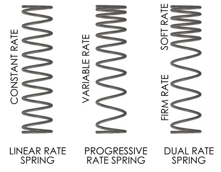
Out of curiosity: what about dual- or variable-rate springs? AIUI, these work by becoming partially or progressively coil-bound as they compress, and thus reducing the effective length and increasing the rate.
Presumably this is also reasonably practical to analyse using a spreadsheet - you just have to be careful that the coils meet before they get too close to yield!
Jul 06, 2015
11:10 AM
- Mark as New
- Bookmark
- Subscribe
- Mute
- Subscribe to RSS Feed
- Permalink
- Notify Moderator
Please log in to access translation
Jul 06, 2015
11:10 AM
I may be mistaken but I think a good variable rate spring design is accomplished by a variable spring diameter and not coil clash:


