- Community
- Creo+ and Creo Parametric
- 3D Part & Assembly Design
- Re: FLATTEN SWEEP?
- Subscribe to RSS Feed
- Mark Topic as New
- Mark Topic as Read
- Float this Topic for Current User
- Bookmark
- Subscribe
- Mute
- Printer Friendly Page
FLATTEN SWEEP?
- Mark as New
- Bookmark
- Subscribe
- Mute
- Subscribe to RSS Feed
- Permalink
- Notify Moderator
FLATTEN SWEEP?
Does anyone know a good way to flatten a sweep of a round bar.
This thread is inactive and closed by the PTC Community Management Team. If you would like to provide a reply and re-open this thread, please notify the moderator and reference the thread. You may also use "Start a topic" button to ask a new question. Please be sure to include what version of the PTC product you are using so another community member knowledgeable about your version may be able to assist.
Solved! Go to Solution.
- Labels:
-
General
Accepted Solutions
- Mark as New
- Bookmark
- Subscribe
- Mute
- Subscribe to RSS Feed
- Permalink
- Notify Moderator
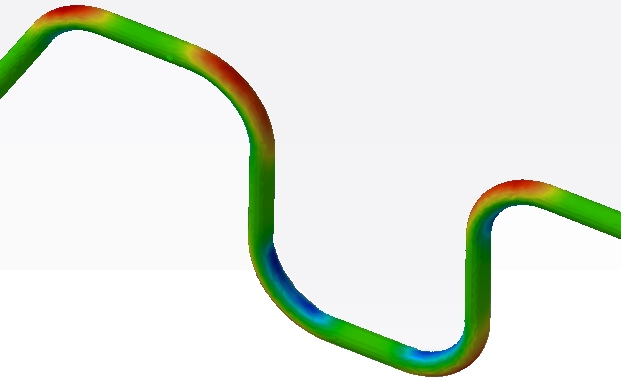
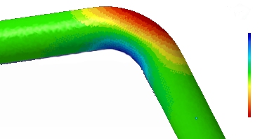
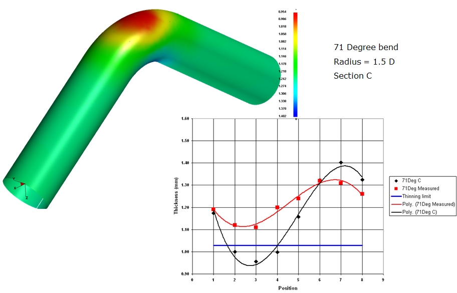
This is all probaly overkill for your question, but here is some information anyway.

With FASTBLANK for Creo, we expect the pipe to have a 0.100" slit in it to allow the software to "open-up" the pipe. If you can add this to your Creo model I'll develop the blank for you. I'll need to know your material properties to be accurate.
Additionally, FormingSuite is able to conduct a formability study on tube bending.


- Mark as New
- Bookmark
- Subscribe
- Mute
- Subscribe to RSS Feed
- Permalink
- Notify Moderator
Guessing that you're looking for a developed length/flat pattern?
I've had good results with an unnamed, superior cad system by modeling the component as sheet metal (not a sweep) whose thickness and width is the diameter of the bar. This will get you the flat length. For appearances sake, apply a full round and there it is.
There is probably an easier way to do this ![]() but it has worked well for me.
but it has worked well for me.
I also tweak the k factor to more like .5, but shop practice will dictate the final value.
- Mark as New
- Bookmark
- Subscribe
- Mute
- Subscribe to RSS Feed
- Permalink
- Notify Moderator
thats what I currently do, I was wondering if there was an easier way or a recommended way from PTC.
- Mark as New
- Bookmark
- Subscribe
- Mute
- Subscribe to RSS Feed
- Permalink
- Notify Moderator
FASTBLANK for Creo is a Finite Element Based program from Forming Technologies www.forming.com to create flat patterns (aka Blank Shapes) from complex geometry. It is primarily intended for sheet metal parts but with an extended material database any geometry can be flattend.
The FASTBLANK for Creo solver takes into account the material properties and accounts for stretch and deformation.
- Mark as New
- Bookmark
- Subscribe
- Mute
- Subscribe to RSS Feed
- Permalink
- Notify Moderator
What exactly are you trying to achieve? it is easy to use a square stock in sheetmetal to represent the tube in order to get a flat length. You can adjust the K or Y factor to your process. If all you need is a number, you can use a perimeter value in a "spine" sketch or use a length analysis feature to capture the data. It all depends on what your end goal is.
- Mark as New
- Bookmark
- Subscribe
- Mute
- Subscribe to RSS Feed
- Permalink
- Notify Moderator
I am just looking for an easy way to get a flat pattern, and overall length. The way Jim Moser suggested is what we are currently doing, and is quite easy, but I was wondering what some other ways might be.
- Mark as New
- Bookmark
- Subscribe
- Mute
- Subscribe to RSS Feed
- Permalink
- Notify Moderator
There is no need to do the sheetmetal approach. Often times I need to know my developed length to cut clearances. I do this in my sketch, in your case, reference the sweep sketch. Unless you want the center axis to be the developed length, you can create a sketch with an offset from the sweep origin. The offset would represent the K or Y-Factor you wish to use.. Use an analysis feature on the sketched curves to obtain your developed length.
- Mark as New
- Bookmark
- Subscribe
- Mute
- Subscribe to RSS Feed
- Permalink
- Notify Moderator
Our shop wants the flat state shown on the drawing, with dimensions to bend lines, so I have to have the flat state. Thats why I'm starting to think the way we are currently doing it is going to be the easiest thing for us.
- Mark as New
- Bookmark
- Subscribe
- Mute
- Subscribe to RSS Feed
- Permalink
- Notify Moderator
If the print could bend it for them, they'd want that too ![]() Give 'em an inch...
Give 'em an inch...
- Mark as New
- Bookmark
- Subscribe
- Mute
- Subscribe to RSS Feed
- Permalink
- Notify Moderator
See if the attached file gives you any ideas. Creo 2.0 full version, dwg and part; no family tables.
- Mark as New
- Bookmark
- Subscribe
- Mute
- Subscribe to RSS Feed
- Permalink
- Notify Moderator
This is all probaly overkill for your question, but here is some information anyway.

With FASTBLANK for Creo, we expect the pipe to have a 0.100" slit in it to allow the software to "open-up" the pipe. If you can add this to your Creo model I'll develop the blank for you. I'll need to know your material properties to be accurate.
Additionally, FormingSuite is able to conduct a formability study on tube bending.


