Community Tip - When posting, your subject should be specific and summarize your question. Here are some additional tips on asking a great question. X
- Community
- Creo+ and Creo Parametric
- 3D Part & Assembly Design
- Re: Fastener Analysis
- Subscribe to RSS Feed
- Mark Topic as New
- Mark Topic as Read
- Float this Topic for Current User
- Bookmark
- Subscribe
- Mute
- Printer Friendly Page
Fastener Analysis
- Mark as New
- Bookmark
- Subscribe
- Mute
- Subscribe to RSS Feed
- Permalink
- Notify Moderator
Fastener Analysis
I have successfully utilized Creo 2.0's ability to apply a preload and force measure features for fasteners in performing a static analysis on an assembly. The Simulate results doesn't seem to have the option to be able to display in the result windows internal tensile and shear forces acting on the fasteners. Does anyone know if Creo simulate has this ability.
I have attached an example of a fastener analysis that was done using ABAQUS. The analysis results display both vonMises stresses as well as the tensile and shear force magnitude vectors. This is what I was hoping Creo can display.
Solved! Go to Solution.
- Labels:
-
Assembly Design
Accepted Solutions
- Mark as New
- Bookmark
- Subscribe
- Mute
- Subscribe to RSS Feed
- Permalink
- Notify Moderator
Hi,
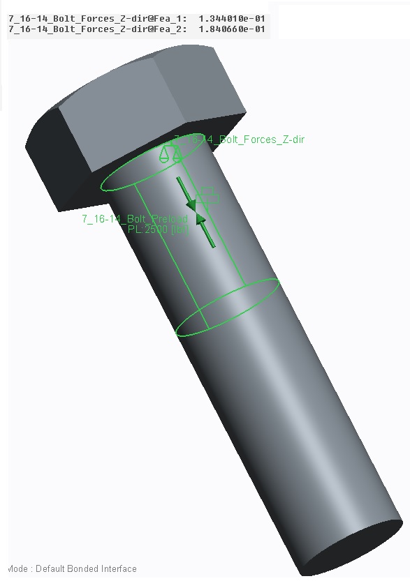
Thank you so much for your response. This was very helpful. I am able to set up a Measure feature in the Simulation mode that calculates a force in the fastener. However the output forces in the summary table are a little confusing. I am obviously not setting up my measure parameters correctly because it looks like the summary output you show is exactly what I am looking for. I would be interested in how you set up your measure commands for outputting separation stress, shear force, shear stress, tensile force, and tensile stress. I am not very familiar with idealized components in Mechanica. Are you setting up fastener connections with assigned preloads in Mechanica versus actually modeling the fastener as part of an assembly (for example). I went the route of assembling fasteners in my assembly and assigning preloads to the fasteners themselves through the Refine Model application and creating a volume region in which the preload and force measure is assigned.
Here are some images of the summary output for the force in my 7/16-14 fastener, the fastener preload setup on the solid model, and the stress display of the fastener in the assembly.


- Mark as New
- Bookmark
- Subscribe
- Mute
- Subscribe to RSS Feed
- Permalink
- Notify Moderator
Hello,
did you look at the run's summary window ?
It is available for fasteners "idealized" in mechanica.
If you want to have a colorful 3D result, you'll have to model a screw and add it in your assembly.
- Mark as New
- Bookmark
- Subscribe
- Mute
- Subscribe to RSS Feed
- Permalink
- Notify Moderator
Hi,
Thank you so much for your response. This was very helpful. I am able to set up a Measure feature in the Simulation mode that calculates a force in the fastener. However the output forces in the summary table are a little confusing. I am obviously not setting up my measure parameters correctly because it looks like the summary output you show is exactly what I am looking for. I would be interested in how you set up your measure commands for outputting separation stress, shear force, shear stress, tensile force, and tensile stress. I am not very familiar with idealized components in Mechanica. Are you setting up fastener connections with assigned preloads in Mechanica versus actually modeling the fastener as part of an assembly (for example). I went the route of assembling fasteners in my assembly and assigning preloads to the fasteners themselves through the Refine Model application and creating a volume region in which the preload and force measure is assigned.
Here are some images of the summary output for the force in my 7/16-14 fastener, the fastener preload setup on the solid model, and the stress display of the fastener in the assembly.


- Mark as New
- Bookmark
- Subscribe
- Mute
- Subscribe to RSS Feed
- Permalink
- Notify Moderator
Shad Davis wrote:
.......
Are you setting up fastener connections with assigned preloads in Mechanica versus actually modeling the fastener as part of an assembly (for example).
.......
Yes, I did.
Once created, analysis results for each fastener connections will be automatically computed.
You can have a look at the Pro/E help files, they are quite well done.
Here is an example of fastener definition (I'm using WF5):
- Mark as New
- Bookmark
- Subscribe
- Mute
- Subscribe to RSS Feed
- Permalink
- Notify Moderator
Hi,
I am also working on same kind of problem.
I have modeled solid bolts with nut and applied preload.
Now i want to check total normal & shear stress at a section of bolt.
Please help me how to create a measure for the same.
Best Regards,
Adi


