Community Tip - Visit the PTCooler (the community lounge) to get to know your fellow community members and check out some of Dale's Friday Humor posts! X
- Community
- Creo+ and Creo Parametric
- 3D Part & Assembly Design
- Re: Flexibility: One of two varied items gets lock...
- Subscribe to RSS Feed
- Mark Topic as New
- Mark Topic as Read
- Float this Topic for Current User
- Bookmark
- Subscribe
- Mute
- Printer Friendly Page
Flexibility: One of two varied items gets locked. (Why?)
- Mark as New
- Bookmark
- Subscribe
- Mute
- Subscribe to RSS Feed
- Permalink
- Notify Moderator
Flexibility: One of two varied items gets locked. (Why?)
I have a part that is a rod with a length and a diameter, both defined as flexible.
I have a couple of family tabled assemblies that use this part, and they both have the flexibility activated for this part.
This is the only part in the assembly, besides a Bulk Item that I need to populate my BOM Table.
The issue is that I will be working along with all going well, and with all instances behaving nicely, and drawings showing correct lengths, when at any given time, the length item becomes locked, and all parts default to the much longer base part length.
I go to Edit Definition of the part, then check the flexibility, and sure enough the length has a big lock just to the right of it, but the diameter is still free.
There is nothing more going on here other than a simple cylindrical shaped part, and to simple family table assys that use it along with bulk items.
I do have a family table of bulk items, and the more complicated of the two assys has a column in the family table controlling which bulk is used with which part.
These parts are all new in my work space, so have not been checked into windchill yet, and they are not marked as read only, so why would the length become locked?
Remember, the diameter dimension always remains free or not locked.
- Labels:
-
2D Drawing
- Mark as New
- Bookmark
- Subscribe
- Mute
- Subscribe to RSS Feed
- Permalink
- Notify Moderator
Which version of software are you using?
Something to add - flexibility is handled by hidden/dynamic family tables. There may be a book-keeping problem that needs to be addressed, hence the version question.
- Mark as New
- Bookmark
- Subscribe
- Mute
- Subscribe to RSS Feed
- Permalink
- Notify Moderator
Are you saying that your assembly has a flexible component in it (namely the cylinder); and this generic has several instances defined in which the size of this cylinder component is changed?
Are you using "associated parameters" to control these flexible components?
I notice that in Creo 3.0 these are automatically created if you try to define columns for assembly instances using dimensions of sub-components. Maybe your version of Creo does not do that?
I know that without using these "associated parameters" I had very strange results in the past including this "locking" behaviour. I can't really explain why or how it happened, but essentially you have to use the associated parameters when trying to control these flexible components from relations or family tables... Anyway, this is just a guess, because I am not sure about several things. It would be best if you provided a representative sample model.
- Mark as New
- Bookmark
- Subscribe
- Mute
- Subscribe to RSS Feed
- Permalink
- Notify Moderator
I am using CREO 2.
1. The base part has a diameter (.5") and a length (26").
Both of which are flexible.
No family table exists at this level
2. I have an assembly of this part and a several bulk materials.
In this assembly is a nested family table consisting of the following:
2a. Fine (4 diameters) each (36" raw material length).
2b. Course (4 diameters) each (48" raw material length).
3. I have another assembly of this part and several bulk materials
In this assembly is another nested family table consisting of the following:
3a. Fine (4 diameters) each at several different (Final cut lengths).
3b. Course (4 diameters) each at several different (Final cut lengths).
4. Finally there are assemblies of these final cut lengths and sheaths.
The sheath part is a family tabled part.
This final assembly is also a family table assembly.
I can set these all up as required, regenerate, save and open and close them with all working as it should.
That is what I tested out on Friday afternoon.
I closed them all down, shut down CREO, then restarted and reopened these assemblies, and drawings several times.
Each time all was as it should be down to the final assembly and drawings in Item 4 above.
Then for no apparent reason, like first thing this morning, I open my final assembly of one of the cut lengths and a sheath, only to find that the base part has reverted back to the original (26") length.
Upon checking the flexibility of the base part, in this same assembly, I find the length to be locked, with the diameter still free to be flexed.
The flexibility settings in the actual base part seem to be fine.
Again, only the length gets locked, with the diameter still allowed to flex.
- Mark as New
- Bookmark
- Subscribe
- Mute
- Subscribe to RSS Feed
- Permalink
- Notify Moderator
Point 1) I take it that you have "predefined" the flexibility of this "rod" model? The varied items table consists of two dimensions, length and diameter?
Points 2 + 3) please post images of the varied items tables for the flexible components in these assemblies, and also the family tables for these assemblies
Point 4) is this then the overall assembly consisting of two sub-assemblies from 2) and 3). Does this assembly also have a family table?
- Mark as New
- Bookmark
- Subscribe
- Mute
- Subscribe to RSS Feed
- Permalink
- Notify Moderator
My manager, who is the closet thing we have to a ProE expert here, and he is very knowledgeable, thought that using the same Flexible Base Part in the two assemblies might be the problem.
We decided to use separate base parts for the Raw Material Assy (item 2) and for the Cut Lengths Assy (item 3).
Since I had all of this checked into Windchill, I had to delete it all because of the single base part existing everywhere.
I now have separate Flexible Base Parts, and separate, disconnected Family Table Assemblies.
I am in hopes that all will be stable now.
If not, I will post back with the items you asked for from the new parts and assemblies.
- Mark as New
- Bookmark
- Subscribe
- Mute
- Subscribe to RSS Feed
- Permalink
- Notify Moderator
Well, whatever works. I don't think that's the optimal solution, since the flexible components can be made to work, but again I mention the requirement for having the associated parameter. Good luck!
- Mark as New
- Bookmark
- Subscribe
- Mute
- Subscribe to RSS Feed
- Permalink
- Notify Moderator
I meant to ask:
Can you clarify a bit more on the subject of Associated Parameters in this context?
- Mark as New
- Bookmark
- Subscribe
- Mute
- Subscribe to RSS Feed
- Permalink
- Notify Moderator
That is why I was asking for you to take screenshots of your situation.
I am not sure but maybe in Creo 2.0 these are not properly tagged as "associated parameters".
This is what I would be expecting to see in your varied items table for the "rod" component:
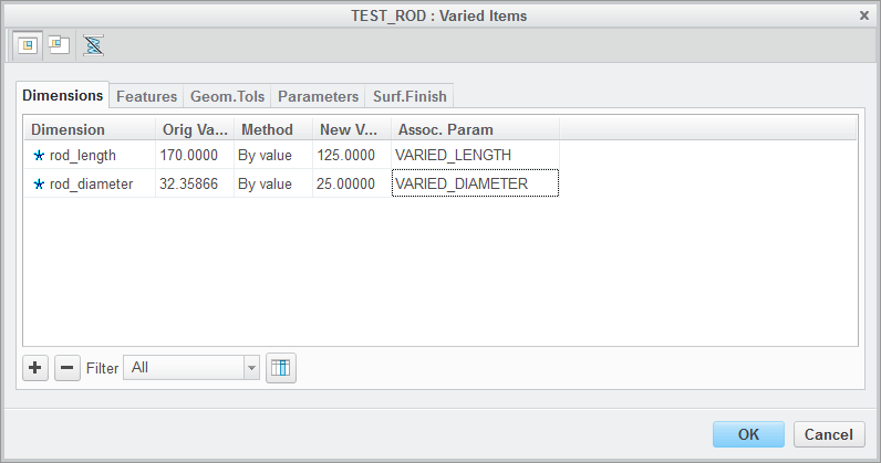
Here, I entered in the names for the associated parameters defined for this component. You don't usually have this column in the table, but you can add it with the button that is right next to the filter combo box.
So then these would be the columns in the assembly's family table:
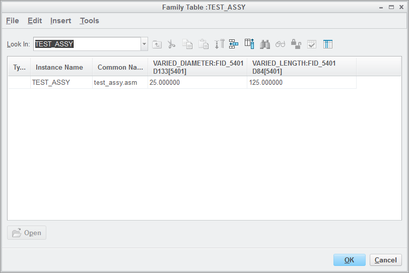
Note that it is the associated parameter that is varying, and not a dimension that belongs to a sub-component with some session ID.
- Mark as New
- Bookmark
- Subscribe
- Mute
- Subscribe to RSS Feed
- Permalink
- Notify Moderator
OK, I am beginning to understand.
I find the way to add an associated parameters column at the assembly level varied items window, but I don't understand what it does.
It just contains the FID info for each dimension, and gives you the opportunity to name the column.
I would like clarification on this.
However, I do not find any way to add the associated parameters, that you show, at the base part level.
- Mark as New
- Bookmark
- Subscribe
- Mute
- Subscribe to RSS Feed
- Permalink
- Notify Moderator
The associated parameters can be used to used to control a particular instance of a flexible-component within an assembly using relations, or through family tables.
I see from the images of your tables, that some kind of an associated parameter was automatically created as you picked the varying dimensions of the cylindrical extrusion. I can't see the entire name (the column isn't expanded), but I assume that it is the same IN_D_1:FID_... in both nested tables.
I don't like this auto-creation, because it gives kind of meaningless column headings (IN_D_1 in your case). I would try redoing the whole exercise and assigning meaningfully named associated parameters to the rod component, prior to building your assembly family tables.
But I'm beginning to suspect that we might be barking up a wrong tree here. Although I tried a toy case using your "nested" family table scheme (I was using two separate assemblies before), and everything seems to work, you already mentioned that things were working fine when one day it all came crashing. This makes me wonder if perhaps some kind of an index or accelerator file related to family tables became corrupt and is causing your headaches. With windchill, it's always important to "verify" as you save, whenever prompted. And also, I'm using Creo 3.0 M130, so maybe PTC fixed things in this release???
- Mark as New
- Bookmark
- Subscribe
- Mute
- Subscribe to RSS Feed
- Permalink
- Notify Moderator
No there is no Associated Perameter column on the varied items list for the base part.
As I said, I do not see any way to add it into the part level.
I can add the column at the assembly level varied items window, but not at the base part level.
The odd thing is that the diameter is always fine, and the length is always what gets locked at the base length.
- Mark as New
- Bookmark
- Subscribe
- Mute
- Subscribe to RSS Feed
- Permalink
- Notify Moderator
The notion of the associated parameter is somewhat meaningless when you are pre-defining the flexibility at the model level.
Associated parameter column can only be added if you edit the varied items table for a flexible component in an assembly (do "edit definition" on the component, and then go to the "Varied items" tab...)
- Mark as New
- Bookmark
- Subscribe
- Mute
- Subscribe to RSS Feed
- Permalink
- Notify Moderator
Time will tell, but I seem to have found a workaround for this issue of the Length getting locked, while the diameter stays free to flex.
The simple fact is that, right or wrong, there has to be some difference between these two dimensions, because it is completely consistent that the length always gets locked while the diameter does not.
Now, the only difference that I could come up with is that, making the rod as an extrusion puts the diameter in the feature sketch, but extrusion length dimension is at the actual feature definition level.
I tried out a theory, that if both were at the sketch level, the issue might not manifest itself.
I made the rod, again, as a revolve, with both the diameter and length at the sketch level.
I made the new family table assembly for all of the cut pieces.
I made a drawing of the one cut piece that I need right now.
I made a drawing of the final component assembly of the cut piece and the sheath.
I saved, regenerated, opened, and closed the files, shutting down CREO between, several times.
I then went home for the day.
I came in this morning, not sure what I would find, but all seems to be stable.
The drawings are good.
The family tabled parts are good.
All seems stable.
I do have the associated perimeter column, for the varied items, on in the assembly, and the dimensions are noted, in that column, as per the base part.
I don't know if that has any bearing but, but again, the diameter, which was in the feature sketch never gave me any issues.
I did the same thing for the stock material part, and am seeing the same success.
I have now done things with these files, and will save, regenerate, and shut down me PC.
Hopefully I will see success when I come back in.
Any theories on the difference of dimensions being at the feature sketch and/or the feature level?
- Mark as New
- Bookmark
- Subscribe
- Mute
- Subscribe to RSS Feed
- Permalink
- Notify Moderator
No theories, just a hunch that Creo 2 has a bug here, as I'm seeing that using an extruded circle worked fine in Creo 3.
I commend you on your perseverance, and I am glad that you have found the work-around.
I think that the procedure of predefining flexibility (including giving meaningful names to the dimensions that are going to be varied), and defining the associated parameters ahead of building the family table will serve you well on future projects.
- Mark as New
- Bookmark
- Subscribe
- Mute
- Subscribe to RSS Feed
- Permalink
- Notify Moderator
Well, that theory did not pan out.
Using the revolve with both dimensions located in the sketch worked with one assembly, but the other assembly still ended up with the length locked again.
This makes me want to agree with you about a bug in CREO 2, because this just isn't consistent.
I tried another idea, and I probably should have done this to start with, but not fully understanding the process of bringing flexibility of an part into an assembly, I just didn't know.
When I originally brought the part into an a family table assembly, and answered yes to wanting to use predefined flexibility, I left asterisks in the new values column of the varied items dialogue box.
After all of this, I went back and changed the new values column to be equal to the original values column, and that has made the difference.
The family table parts seem to be acting nicely now, and staying put at their family table values.
Again, the values in the family table didn't change, but the length would get locked in the flexibility/varied items list, and force the instances to be the length of the base part.
Now they seem to be stable at the family tabled values.
-------------------------------------------
On another note;
I was able to upgrade my PTC Support account, and can now get into the tutorials.
I found one that shows how to create the Associated Parameters that were spoken of earlier in this thread, but I don't quite understand parts of it.
I am going to start a new thread to post those instructions and ask for clarification on a few things.
- Mark as New
- Bookmark
- Subscribe
- Mute
- Subscribe to RSS Feed
- Permalink
- Notify Moderator
Hmm, so in Creo 2.0, the system let you define an associated parameter for flexible component whose "New Value" is specified as * (default value) ?
Strange, because in Creo 3.0, as soon as you define the associated parameter name, the "New Value" which was defined as * changes to the value of the original...
And if you try to change this back to a *, then you get this message:
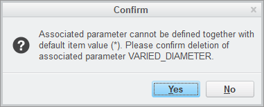
So it seems you found the source of the Creo 2.0 bug related to the flexible components and their use in a family table situations...
- Mark as New
- Bookmark
- Subscribe
- Mute
- Subscribe to RSS Feed
- Permalink
- Notify Moderator
No, No, No,
I didn't use associated parameters.
I simply set the new value of the varied items to the original, base part values, when asked if I wanted to use predefined flexibility, as I brought the part into the assembly.
This is the step that I had missed originally.
I had been leaving the asterisk in place for the new values, and that seemed to be confusing CREO.
Further, I went back, created a brand new work space, and loaded all items from Wind Chill into it.
I then took the one base part and turned it back, from the new revolve, to the original extrusion.
I then used this base part in both of my family table assemblies, and it works perfectly.
I have no associated parameters anywhere.
I only have the varied items set to the base part values in the assemblies.
The only issue that I had was getting the diameter and length columns to stay put in the assembly family tables.
I would put them in, verify the table, regen the part, save the part, then go into the family table and they would be gone.
I really don't know what I ever did to get them to stay, but they seem to be rock solid now.
Again, any theories on this last bit?
- Mark as New
- Bookmark
- Subscribe
- Mute
- Subscribe to RSS Feed
- Permalink
- Notify Moderator
I think you do have associated parameters in your model; edit the definition of your flexible component, and go to the "Flexiblility" tab, open the varied items table, and then show the Assoc. Param column. You should see that the system created these for you, looking at the screenshots you provided, they will be named something like IN_D_1...
- Mark as New
- Bookmark
- Subscribe
- Mute
- Subscribe to RSS Feed
- Permalink
- Notify Moderator
I know for a fact that there are no associated parameters column in the varied items table.
I have checked several times, and it is still located on the left side of the selection window.
I can add it, but it is not there by default, and since I had no idea how to use them, I did not put them in.
Again, as I have said, the only thing I did was to set the new values "=" the original values.
- Mark as New
- Bookmark
- Subscribe
- Mute
- Subscribe to RSS Feed
- Permalink
- Notify Moderator
I think something is being lost in translation.
What does your assembly family table look like? If you have columns that have names such as IN_D_1:FID_XXXX, then you are using the associated parameters.
Otherwise, I don't understand how you can have columns in your assembly level family table that control component's feature dimensions.
For sake of completeness, I post a Creo 2 (M230) model of my "flexible" assembly. See if you can open it and replicate the situations shown in these few screenshots:
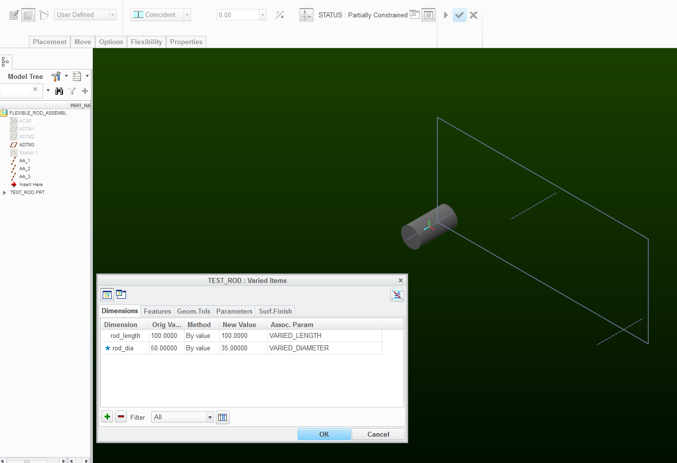
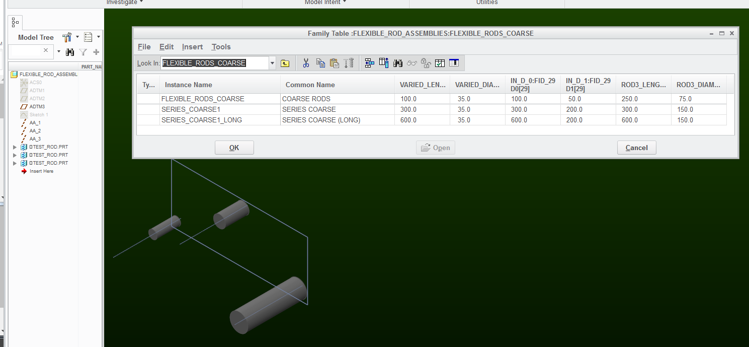
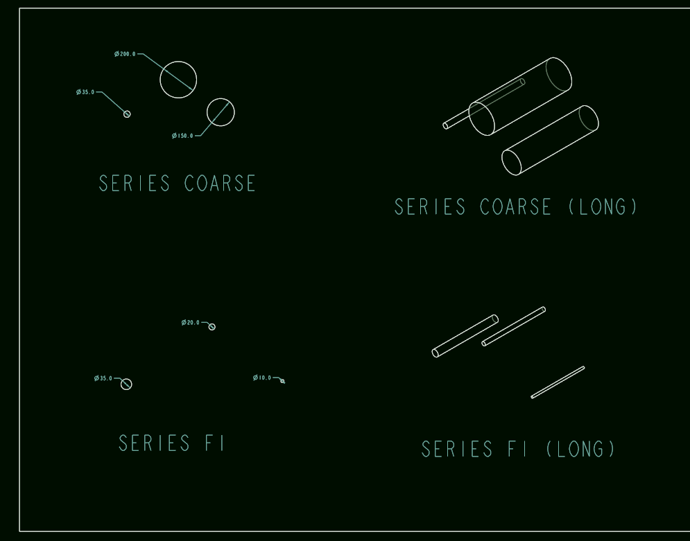
- Mark as New
- Bookmark
- Subscribe
- Mute
- Subscribe to RSS Feed
- Permalink
- Notify Moderator
Yes, you are correct, in that my family table does have those two "IN_D_X:FID_XX" Columns, as you can see in my family table below.
There are, however. no associated parameter columns in my family table as there are in yours above:
There are, in fact, no other columns addressing these dimensions in my family table.
Again, the only thing I did to make this work, was to replace the ASTERISKS, in the NEW VALUES column of the varied items window, with the original base part dimensions.
Oh yes, you will see a ( +/- T7 ) row in my Varied Items window.
This is the tolerance for the length (24+/-6).
You kept referring to the Associated Parameters in the varied items window in "EDIT DEFINITION / VARIED ITEMS".
They are not there either, and as I have stated above, they are not addressed in my family table at all as you did in yours, also shown below.
If I understand you correctly, this should not be working.
Is that correct?
What am I missing?
BTW: I just went in, this morning, and checked my assemblies, and drawings, and all parts are as they should be for a third day of shutting down and restarting.
TOP LEVEL FAMILY TABLE:
NESTED FAMILY TABLE (FINE):
VARIED ITEMS WINDOW IN "EDIT DEFINITION / VARIED ITEMS" OF THE BASE PART INSERTED INTO THE ASSEMBLY
- Mark as New
- Bookmark
- Subscribe
- Mute
- Subscribe to RSS Feed
- Permalink
- Notify Moderator
your screenshot for "VARIED ITEMS WINDOW IN "EDIT DEFINITION / VARIED ITEMS" OF THE BASE PART INSERTED INTO THE ASSEMBLY" - it shows a table, but the "assoc. parameter" column isn't being displayed in it... But from what you are saying, even if you display this column, then it is still blank?
Then that is the strange thing - because I checked and Creo 2.0 M230 behaves just as Creo 3.0 in these respects; Namely, there is no need to manipulate any asterisks because the system gets rid of them as soon as:
a) you define an associated parameter in the varied items table
b) use a dimension of flexible component in a family table
Just for curiosity, what build of Creo 2.0 are you using? And I think we beat this thing to death by now and I think you can safely use the procedure you developed.
However, I still think it's better to define your own associated parameters, because down the line, it's easier to read a family table that has a column called "DIAMETER:FID_xxx" instead of a column called IN_D_8:FID_xxx (I know you took care of that concern by using comment rows)
- Mark as New
- Bookmark
- Subscribe
- Mute
- Subscribe to RSS Feed
- Permalink
- Notify Moderator
I just went in and added the Associated Parameters column and it contains the IN_D_X notations, for the length and diameter.
- Mark as New
- Bookmark
- Subscribe
- Mute
- Subscribe to RSS Feed
- Permalink
- Notify Moderator
BTW, yes I did have the flexibility for Diameter and Length predefined in the base part.
When I brought the base part into each of the two family table assemblies, I said yes when asked if I wanted to use the predefined flexibility.
Then, when the varied items window was displayed, I left the varied items as is, with the original asterisks.
These flexible dimensions were then placed into columns of the secondary Fine and Coarse nested family tables.
- Mark as New
- Bookmark
- Subscribe
- Mute
- Subscribe to RSS Feed
- Permalink
- Notify Moderator
I agree, completely, that this is probably not the optimal solution, but I have spent way too much time on this as it is, and have to move on to complete other work.
That said, however, I really would like to know what was causing the lock on the length dimension.
The only thing different about the two dimensions is that the diameter is created in the protrusion sketch, while the length is entered at the feature level for the extrusion
This should not cause any difference in the dimensions, yet only the length was ever effected, while the diameter always worked perfectly.
- Mark as New
- Bookmark
- Subscribe
- Mute
- Subscribe to RSS Feed
- Permalink
- Notify Moderator
Below you will find all of the images that you asked for.
Yes the final level is a family table, but this table only contains two component columns.
There are no varied dimensions at that level.
---------------------------------------
OK, I deleted all of the original items from windchill.
I started a new work space.
I created a new base part, just like before.
I made an assembly of this part and a bulk item.
I filled out the assy family table as shown below.
I made a drawing of one of the cut lengths.
I made an assy of the one of these cut lengths, and a sheath.
I made it a family table of the two components.
I made a drawing of this assembly.
At this time, I went back to my old work space to empty it and delete it.
When I came back to the new work space, the length of family tabled parts had reverted back to the full 26' length.
Be aware that as before, the diameter is not effected.
Also, the values in the family table do not get changed.
The part simply ignores the length values and reverts to the base length of 26"
One more thing;
I went back and fully defined the flexibility in the top level and both nested tables of the assembly, but nothing changed
The parts were still all defaulted to the original 26" length
------------------------------------------------
BASE PART FLEX TABLE
d0 26 Is the length
d1 .50 is the diameter
FAMILY TABLE ASSEMBLY
TOP LEVEL FAMILY TABLE
NESTED "FINE"FAMILY TABLE
NESTED "COURSE" FAMILY TABLE
ASSEMBLY FLEX VARIED ITEMS TABLE (FROM EDIT DEFINITION)
I hope this can help shed some light.


