- Community
- Creo+ and Creo Parametric
- 3D Part & Assembly Design
- Re: Folding or bending of steel full bar
- Subscribe to RSS Feed
- Mark Topic as New
- Mark Topic as Read
- Float this Topic for Current User
- Bookmark
- Subscribe
- Mute
- Printer Friendly Page
Folding or bending of steel full bar
- Mark as New
- Bookmark
- Subscribe
- Mute
- Subscribe to RSS Feed
- Permalink
- Notify Moderator
Folding or bending of steel full bar
Hello
How is it possible to simulate the force required to bend this
steel bar under the terms of the attached drawing.
You must enter the information of the steel to exceed the elastic limit.
Simulate 3.0 is it able to do
Kind regards.
Denis
- Labels:
-
2D Drawing
- Mark as New
- Bookmark
- Subscribe
- Mute
- Subscribe to RSS Feed
- Permalink
- Notify Moderator
- Mark as New
- Bookmark
- Subscribe
- Mute
- Subscribe to RSS Feed
- Permalink
- Notify Moderator
Hello Paul,
Thank you for this video.
But the bar does not slide, it remains fixed in the wall.
It's just the part B - C which must bend turn to point B.
And the question is how much force should be applied to achieve this result?
Kind regards.
Denis.
- Mark as New
- Bookmark
- Subscribe
- Mute
- Subscribe to RSS Feed
- Permalink
- Notify Moderator
Hi,
question:
You can use measures
Regards
Paul
- Mark as New
- Bookmark
- Subscribe
- Mute
- Subscribe to RSS Feed
- Permalink
- Notify Moderator
Hello
No, because at the moment the question is moot.
Kind regards.
Denis
- Mark as New
- Bookmark
- Subscribe
- Mute
- Subscribe to RSS Feed
- Permalink
- Notify Moderator
Denis,
it is not trivial, in simulate
Not possible in simulate because plastic collapse.
Regards
Paul
- Mark as New
- Bookmark
- Subscribe
- Mute
- Subscribe to RSS Feed
- Permalink
- Notify Moderator
Denis,
Maybe you can have a try by following these steps:
First,you should know the vertical distance between point C and point C' when the bar bends down;
Then set a forced displacement(prescribed translation) which equals that distance;
The third,make a force measure of the forced displacement,hope these can help you!
- Mark as New
- Bookmark
- Subscribe
- Mute
- Subscribe to RSS Feed
- Permalink
- Notify Moderator
The Problem is the plastic collapse, for exmaple:

Regards
Paul
- Mark as New
- Bookmark
- Subscribe
- Mute
- Subscribe to RSS Feed
- Permalink
- Notify Moderator
Hello Paul,
Thanks for this example.
You mean the plasticization of beams in soul full in flexion.
Simulate can't go this far in the calculations.
Kind regards.
Denis.
- Mark as New
- Bookmark
- Subscribe
- Mute
- Subscribe to RSS Feed
- Permalink
- Notify Moderator
"Simulate can't go this far in the calculations"
yes (no global collapse).
Regards
Paul
- Mark as New
- Bookmark
- Subscribe
- Mute
- Subscribe to RSS Feed
- Permalink
- Notify Moderator
- Mark as New
- Bookmark
- Subscribe
- Mute
- Subscribe to RSS Feed
- Permalink
- Notify Moderator
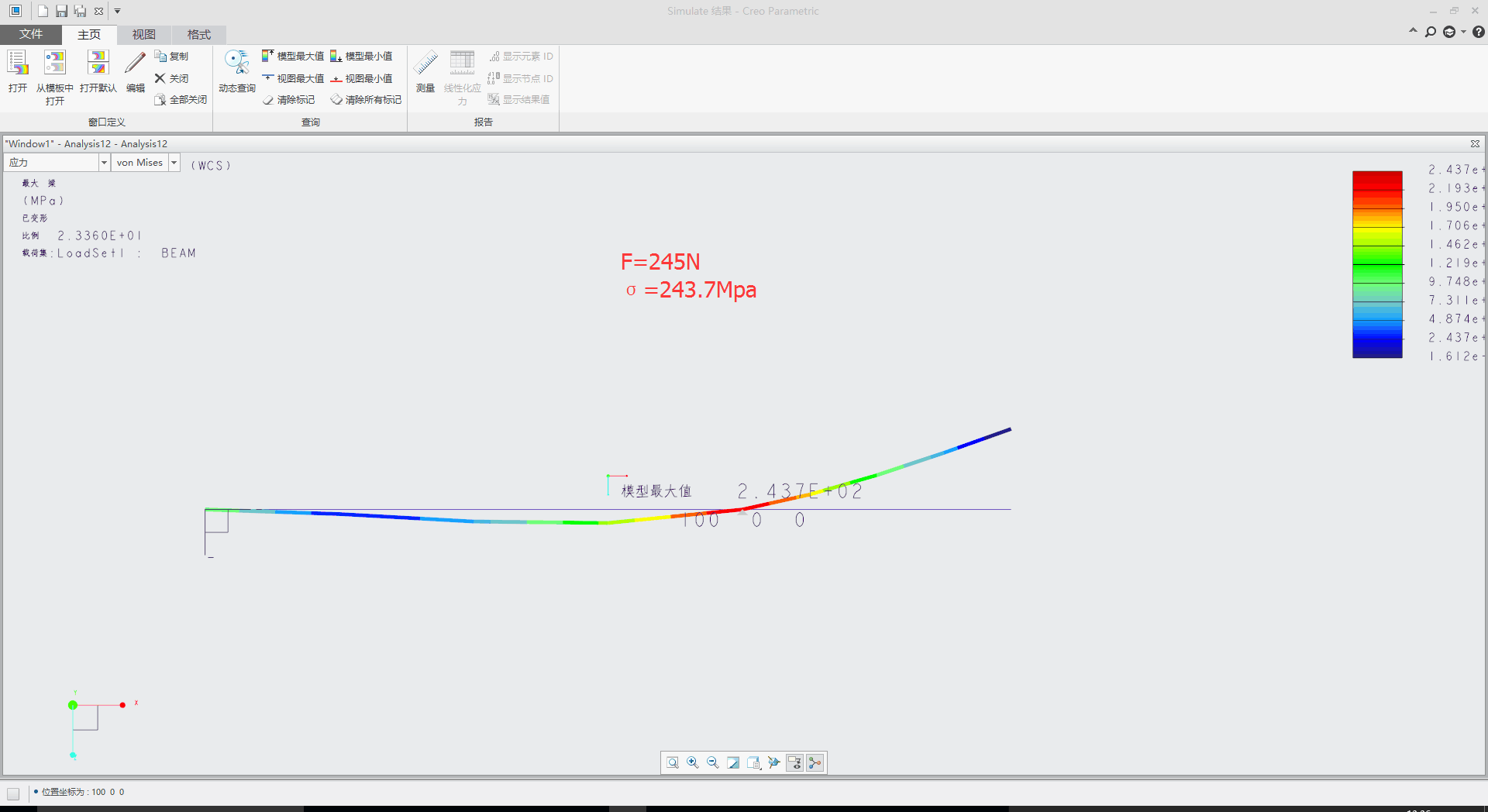
51O%DD~[~OSST}{KL.png)

VM.png)
The size of the force is 245N
you can use optimized design studies
- Mark as New
- Bookmark
- Subscribe
- Mute
- Subscribe to RSS Feed
- Permalink
- Notify Moderator
Hello 学 蒋
Thank you for your response.
The blockages on the axis you do on "points"?
You have used the method of optimized design studies?
Kind regards.
Denis
- Mark as New
- Bookmark
- Subscribe
- Mute
- Subscribe to RSS Feed
- Permalink
- Notify Moderator
"blockages " means constraint?

I used the optimized design
The beam.prt.1 can be opened by creo 4.0
- Mark as New
- Bookmark
- Subscribe
- Mute
- Subscribe to RSS Feed
- Permalink
- Notify Moderator
Hello
Thank you for your shipment.
Yes, blocking means forced.
I'm on W7 32-bit pro, I do not yet use Creo 4.0, so that I
buy a PC 64 bit with W10 pro.
Kind regards.
Denis.
- Mark as New
- Bookmark
- Subscribe
- Mute
- Subscribe to RSS Feed
- Permalink
- Notify Moderator
Hello
Here's another demo done with 64-bit software.
Kind regards.
Denis.
- Mark as New
- Bookmark
- Subscribe
- Mute
- Subscribe to RSS Feed
- Permalink
- Notify Moderator
Yes, Denis, it is possible to analyze this, but you will have to use solid elements with material plasticity, and also large deformation analysis + contact analysis. If you want to model the plastic collapse, you cannot model the load using a "load", instead, you will need to model the load using an enforced displacement.
The nonlinear solver is sensitive to mesh, I advise to use brick/wedge elements to model the beam.
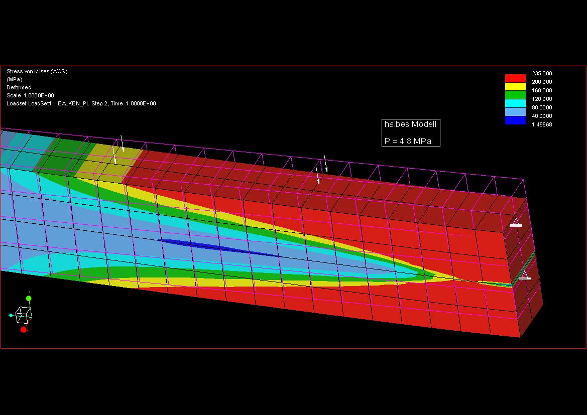
Here are a few pictures from a plastic collapse analysis I did a few years ago. I recall that I also had an animation, but I can't seem to find it. Unfortunately I can't run Creo where I sit now, so I can't re-create these results.
In this case I have no contacts, but the load is axial, and what you see here is post-critical behavior, if you enforce a vertical displecement, along the edge of the beam end.
/Mats L/
- Mark as New
- Bookmark
- Subscribe
- Mute
- Subscribe to RSS Feed
- Permalink
- Notify Moderator
Hello masts,
Thank you for your response and your explanations.
I put the demonstration in GIF, because the link is no longer valid.
Kind regards.
Denis


