- Community
- Creo+ and Creo Parametric
- 3D Part & Assembly Design
- Re: Gear design and layers
- Subscribe to RSS Feed
- Mark Topic as New
- Mark Topic as Read
- Float this Topic for Current User
- Bookmark
- Subscribe
- Mute
- Printer Friendly Page
Gear design and layers
- Mark as New
- Bookmark
- Subscribe
- Mute
- Subscribe to RSS Feed
- Permalink
- Notify Moderator
Gear design and layers
I'm following this link How to model spur gear in CAD to create an involute gear profile but the base dia, pitch dia, outer dia and curve are all different layers so when I try and create the points needed for the next steps in creating the "tooth" the geometry is non selectable for the point to snap at the various intersections and points. So this is probably a layer question where I would like to edit the layers "beneath" the sketch or bring the geometry forward so I can edit within a sketch. I'm using creo 3.
This thread is inactive and closed by the PTC Community Management Team. If you would like to provide a reply and re-open this thread, please notify the moderator and reference the thread. You may also use "Start a topic" button to ask a new question. Please be sure to include what version of the PTC product you are using so another community member knowledgeable about your version may be able to assist.
- Labels:
-
Surfacing
- Tags:
- gear design
- Mark as New
- Bookmark
- Subscribe
- Mute
- Subscribe to RSS Feed
- Permalink
- Notify Moderator
Give us a hint - the steps are numbered - which step is sticking (I'm guessing 5 or 6)
Aside from that, I suspect that you have the selection filter set to something besides ALL, because otherwise you would be saying you could not see the curves to select them.
The Layer concept in Creo is that it is a list, usually to manage visibility, not as geometry overlays that bitmap graphics have, so there is no 'beneath' to them.
If you can see the geometry you can select it.
If you can't see the geometry, then you can change the visibility of the layers under the layers menu.
- Mark as New
- Bookmark
- Subscribe
- Mute
- Subscribe to RSS Feed
- Permalink
- Notify Moderator
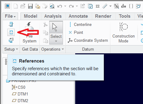
First define the references. After that, new features will snap to them within a sketch.

You can always make them members of the same layer, but be careful if some operations are done using layer filtering/selection.
- Mark as New
- Bookmark
- Subscribe
- Mute
- Subscribe to RSS Feed
- Permalink
- Notify Moderator
Guys, thank you. Got the technique right hold down Alt key then select points and finally got the point tool to snap. My problem now is step 9. I cannot work out how to create the extrude. The strange dollar sign that would appear to lock the shape as one - any ideas??
- Mark as New
- Bookmark
- Subscribe
- Mute
- Subscribe to RSS Feed
- Permalink
- Notify Moderator
The dollarsignthingy is the symbol used for a projected curve from within the sketch of an edge or curve defined before the sketch..
- Mark as New
- Bookmark
- Subscribe
- Mute
- Subscribe to RSS Feed
- Permalink
- Notify Moderator
Hello Tom Clark
thanks for sharing How to model spur gear in CAD .
http://www.beyondmech.com/ looks like great informations source.
Hope you will be succesfull with gearings.
Regards


