Community Tip - You can subscribe to a forum, label or individual post and receive email notifications when someone posts a new topic or reply. Learn more! X
- Community
- Creo+ and Creo Parametric
- 3D Part & Assembly Design
- Re: Harness for Manufacturing needs modernising
- Subscribe to RSS Feed
- Mark Topic as New
- Mark Topic as Read
- Float this Topic for Current User
- Bookmark
- Subscribe
- Mute
- Printer Friendly Page
Harness for Manufacturing needs modernising
- Mark as New
- Bookmark
- Subscribe
- Mute
- Subscribe to RSS Feed
- Permalink
- Notify Moderator
Harness for Manufacturing needs modernising
Problem #1 is users flattening from the end of a connector. Result: complete redo of the harness mfg and drawing. Suggestion, rethink the process of making the features into one of assembling sections together. So you have a much more robust result. It probably sounds crazy but i've seen people spend an hour rebuilding the data chain just for a 2 connector single conductor lead drawing.
Problem #2 is conductors not being long enough to properly flatten. Result: users mess about in 3D or at manufacturing to make a good enough result. Suggest having the harness for manufacturing allowing a bit of looseness when flattening. e.g. if it's 2mm short let it stick that wire in anyway.
Problem #3 is how the flattened harness colors in a drawing. Black wires start dissappearing into a black background (they do print of course). Suggest an option where 'contrast' appears to be being violated the system overrides the entity color with geometry instead.
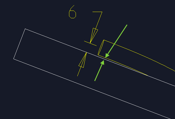
Problem #4 is how the cable geometry isn't treated like normal geometry especially in a drawing. If you want to define the distance from a cable outer jacket to a wall, we think this should be changed and here's a picture of what we mean.

- Labels:
-
Routed Syst. Design
- Mark as New
- Bookmark
- Subscribe
- Mute
- Subscribe to RSS Feed
- Permalink
- Notify Moderator
In Creo 3.0 harness mfg is re-design to modernized.
- Mark as New
- Bookmark
- Subscribe
- Mute
- Subscribe to RSS Feed
- Permalink
- Notify Moderator
Harnessing in 3.0 is still garbage.. Cabling is the worst CAD package I've used in the past 20 years. A modern work flow would still be welcomed.
- Mark as New
- Bookmark
- Subscribe
- Mute
- Subscribe to RSS Feed
- Permalink
- Notify Moderator
AWESOME, i look forward to seeing it.


