
Turn on suggestions
Auto-suggest helps you quickly narrow down your search results by suggesting possible matches as you type.
Showing results for
Please log in to access translation
Turn on suggestions
Auto-suggest helps you quickly narrow down your search results by suggesting possible matches as you type.
Showing results for
- Community
- Creo+ and Creo Parametric
- 3D Part & Assembly Design
- Harness manufacturing
Translate the entire conversation x
Please log in to access translation
Options
- Subscribe to RSS Feed
- Mark Topic as New
- Mark Topic as Read
- Float this Topic for Current User
- Bookmark
- Subscribe
- Mute
- Printer Friendly Page
Harness manufacturing
May 08, 2020
01:59 PM
- Mark as New
- Bookmark
- Subscribe
- Mute
- Subscribe to RSS Feed
- Permalink
- Notify Moderator
Please log in to access translation
May 08, 2020
01:59 PM
Harness manufacturing
Hi,
i'm new on CREO (3 month). new job new company.
i used to work on different software to create 3D harnesses.
i have an issue today regarding Harness Mfg. we just got the licence
i try to flatten simple harness. it work (sometime) but when i want to use a component
to route my harness sometime it will work and sometime i got the following message:
Unsupported Axial Topology
when i remove the component from the path it will be ok, but i use the same component
somewhere else and it is working fine so i don't understand what is happening.
i think the part i use to route the wire is created properly as it is working fine somewhere else
if someone has an idea i will appreciate.
Thanks
Ced1
4 REPLIES 4
May 10, 2020
07:50 PM
- Mark as New
- Bookmark
- Subscribe
- Mute
- Subscribe to RSS Feed
- Permalink
- Notify Moderator
Please log in to access translation
May 10, 2020
07:50 PM
Hi Ced, first off, there are 3 different package levels for HMX which can cope with increasingly complex harness/cabling situations. The topic of splices is a difficult one for programs to work out where they should flatten to from a 3D harness. 'Unsupported' would say to me that the package level of HMX is stopping it from working, and not that it doesn't know what to do.
The error message is a bit cryptic (such is life these days it seems), if it helps, topology refers to the way the harness branches out to various connectors/splices/parts e.g.in your case, 1 network location has 1 wire going to a splice, while the other wire from the same location goes to the next network location but doesn't appear to meet in the same place. There are a few ways that the program can flatten/group bundles (as shown in my doodle) and i think this is the topology problem.
Have used the splice as an 'inserted component' or a 'designated connector'?
Have you tried inserting an additional network location and snapping the splice to it i.e. if you can tell it which bundle/location the splices belongs to, rather than hanging in free space, it should be able to resolve the topology problem.
I'm sure there is nothing wrong with the component itself, but was that in cases with no branches? (1 to 1 in-line splice)
May 13, 2020
08:11 AM
- Mark as New
- Bookmark
- Subscribe
- Mute
- Subscribe to RSS Feed
- Permalink
- Notify Moderator
Please log in to access translation
May 13, 2020
08:11 AM
Hi and thanks for your answer,
we got the HMX advanced lvl, and i used the splice as designated connector, and we also use creo Schematics.
i tried to use the splice to connect different wires from different connectors where one side of the splice will have 2 ENTRY_PORTS (with ROUND type as i want different wires coming in) and the other side will have 1 (ROUND type).
i just create the wire using an XML (created from schematics) and then use some clamps (taking their axes or CSYS) to manage the routing. so i don't have to create a network.
i was able to flatten if i create a location point right before and after the splice (as mentioned in PTC help)
so i'm guessing that the total length from the wires with the splice should be (almost) same as the wire without the splice for the program to consider that they are both on the same path. otherwise the program does not know what to do.
so your idea the create a network might help actually for some portion of the routing where i need to have the splices located. it will control the path for all wires with no splice and the wires with splices.
i have to try it.
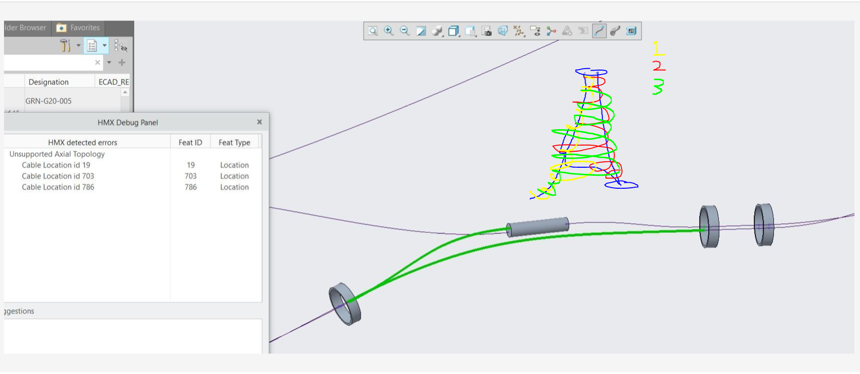
but now, if u see the new picture attached, when i have the wires (blue) connected to the splice (2 bottom, 1 top), i can flatten and i have to correct length for all the wires. in wire list
when i want to include the new wire (red one) then i have an issue with topology -->
Topology cannot be resolved. review the routing in the 3D harness model and resolve issues.
then HMX closed without more detail.
if i remove the 'red one' everything is fine.
any idea for this case?
Thanks again for you time and answer.
May 17, 2020
08:48 PM
- Mark as New
- Bookmark
- Subscribe
- Mute
- Subscribe to RSS Feed
- Permalink
- Notify Moderator
Please log in to access translation
May 17, 2020
08:48 PM
Hrm, although this isn't really solving your issue, can i ask why the 2 entry ports on one side and 1 on the other? Typically splices are inline (e.g. M81824/1-3) but obviously there are many exceptions, what is the physical part you are modeling here?
What I'm trying to get at is there a physical routing reason rather than just having 1, unless there is a large physical separation between entry points the cut length of wires will be negligible between the entries.
Are you also aware of the differences beetween entry types? WIRE entry type allows 1 wire, but ROUND and STRAIGHT allow unlimited. ROUND adds additional wires in a spiral pattern, whereas STRAIGHT is a straight line. Where the wire comes from is irrelevant for any entry port, it just sets the way the bundling works.
Can you try selecting the red wire and re-routing it with the right blue wire group? (i think the right click option is re-route?)
May 19, 2020
01:39 PM
- Mark as New
- Bookmark
- Subscribe
- Mute
- Subscribe to RSS Feed
- Permalink
- Notify Moderator
Please log in to access translation
May 19, 2020
01:39 PM
Hi,
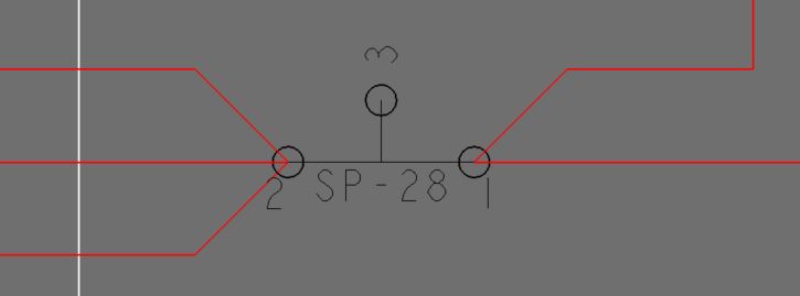
i was trying to separate all wires with 2 entry port because in schematic i have created this type of splice.
see picture. so to make it consistent for cabling i had to create 3 entry ports.
But i found that it will not work for flattening apparently.
because when i link all wires to 1 entry port on 1 side and others to 2nd entry port, then flattening will work.
so i had to modify all my schematic and now everything is working.
only one entry port on each side of the splice, one location point before and after splices.
still have some issue, but more time i spent on it, more i understand the way it will work.
thanks.


