
Turn on suggestions
Auto-suggest helps you quickly narrow down your search results by suggesting possible matches as you type.
Showing results for
Please log in to access translation
Turn on suggestions
Auto-suggest helps you quickly narrow down your search results by suggesting possible matches as you type.
Showing results for
Community Tip - Your Friends List is a way to easily have access to the community members that you interact with the most! X
- Community
- Creo+ and Creo Parametric
- 3D Part & Assembly Design
- Help! Equation Solution Request.
Translate the entire conversation x
Please log in to access translation
Options
- Subscribe to RSS Feed
- Mark Topic as New
- Mark Topic as Read
- Float this Topic for Current User
- Bookmark
- Subscribe
- Mute
- Printer Friendly Page
Help! Equation Solution Request.
Jun 13, 2013
05:29 PM
- Mark as New
- Bookmark
- Subscribe
- Mute
- Subscribe to RSS Feed
- Permalink
- Notify Moderator
Please log in to access translation
Jun 13, 2013
05:29 PM
Help! Equation Solution Request.
How do I "define" a semi-circle by an equation when Y is linear?
I know the cartesian formula:
x = 4 * cos ( t * 180 )
y = 4 * sin ( t * 180 )
z = 0
But I need to compensate for the trajectory (Y) which has a linear value.
I need the formula applied only to X given Y is linear 0-1.
I want to sweep a VSS to make this shape. The trajpar is the given value (t as Y):
This thread is inactive and closed by the PTC Community Management Team. If you would like to provide a reply and re-open this thread, please notify the moderator and reference the thread. You may also use "Start a topic" button to ask a new question. Please be sure to include what version of the PTC product you are using so another community member knowledgeable about your version may be able to assist.
Solved! Go to Solution.
Labels:
- Labels:
-
General
ACCEPTED SOLUTION
Accepted Solutions
Jun 19, 2013
02:45 AM
- Mark as New
- Bookmark
- Subscribe
- Mute
- Subscribe to RSS Feed
- Permalink
- Notify Moderator
Please log in to access translation
Jun 19, 2013
02:45 AM
Dear Antonius
I have tried to create SEMICIRCLE BY SWEEP feature  - it is working (you can investigate my model)
Note: I have used for sweep feature the Relation (for UPPER_HALF_OF_THE_SEMICIRCLE) sd4=(r^2 - (trajpar*r)^2) ^ (1/2)
Regards,
Best Regards,
Vladimir Palffy
Vladimir Palffy
30 REPLIES 30
Jun 14, 2013
01:37 AM
- Mark as New
- Bookmark
- Subscribe
- Mute
- Subscribe to RSS Feed
- Permalink
- Notify Moderator
Please log in to access translation
Jun 14, 2013
01:37 AM
Dear Antonius,
I think that you can combine Sweep feature with Graph feature - the values of graph will be inputs for sweep trajpar relations.
Regards,
Best Regards,
Vladimir Palffy
Vladimir Palffy
Jun 14, 2013
11:55 AM
- Mark as New
- Bookmark
- Subscribe
- Mute
- Subscribe to RSS Feed
- Permalink
- Notify Moderator
Please log in to access translation
Jun 14, 2013
11:55 AM
...or that  The graph works nicely but there has to be a way to do the math.
Jun 15, 2013
02:58 AM
- Mark as New
- Bookmark
- Subscribe
- Mute
- Subscribe to RSS Feed
- Permalink
- Notify Moderator
Please log in to access translation
Jun 15, 2013
02:58 AM
Hi Antonius,
Maybe "Mathcad" community able to help you: http://communities.ptc.com/community/mathcad
Jun 18, 2013
12:49 PM
- Mark as New
- Bookmark
- Subscribe
- Mute
- Subscribe to RSS Feed
- Permalink
- Notify Moderator
Please log in to access translation
Jun 18, 2013
12:49 PM
I think the Mathcad community considers us an odd bunch and I rarely get replies... go figure 
Jun 18, 2013
12:42 PM
- Mark as New
- Bookmark
- Subscribe
- Mute
- Subscribe to RSS Feed
- Permalink
- Notify Moderator
Please log in to access translation
Jun 18, 2013
12:42 PM
I'd love to help, but I suck at math! I'd be graphing that baby!
Jun 18, 2013
12:47 PM
- Mark as New
- Bookmark
- Subscribe
- Mute
- Subscribe to RSS Feed
- Permalink
- Notify Moderator
Please log in to access translation
Jun 18, 2013
12:47 PM
I think that is why we are "visual" people... Geometry is so much simpler to "grasp" - literally 
Jun 18, 2013
01:34 PM
- Mark as New
- Bookmark
- Subscribe
- Mute
- Subscribe to RSS Feed
- Permalink
- Notify Moderator
Please log in to access translation
Jun 18, 2013
01:34 PM
Exactly! Same result, just visual!
Jun 19, 2013
02:45 AM
- Mark as New
- Bookmark
- Subscribe
- Mute
- Subscribe to RSS Feed
- Permalink
- Notify Moderator
Please log in to access translation
Jun 19, 2013
02:45 AM
Dear Antonius
I have tried to create SEMICIRCLE BY SWEEP feature - it is working (you can investigate my model)
Note: I have used for sweep feature the Relation (for UPPER_HALF_OF_THE_SEMICIRCLE) sd4=(r^2 - (trajpar*r)^2) ^ (1/2)
Regards,
Best Regards,
Vladimir Palffy
Vladimir Palffy
Jun 19, 2013
01:33 PM
- Mark as New
- Bookmark
- Subscribe
- Mute
- Subscribe to RSS Feed
- Permalink
- Notify Moderator
Please log in to access translation
Jun 19, 2013
01:33 PM
That's the one! I suspected I would have to divide it into quarters.
Here is the simplified "on the fly" version: sd4=sqrt((5^2 - (trajpar*5)^2))
And as a bonus, it covers ellipses
Thanks Vladimir!
Jun 19, 2013
01:36 PM
- Mark as New
- Bookmark
- Subscribe
- Mute
- Subscribe to RSS Feed
- Permalink
- Notify Moderator
Please log in to access translation
Jun 19, 2013
01:36 PM
Gopal, you didn't have to remove your reply. It is definitely worthy of this discussion:
That's the formula of a circle x^2+y^2=radius^2
with value of Y varying from with trajectory parameter.
Jun 21, 2013
04:27 AM
- Mark as New
- Bookmark
- Subscribe
- Mute
- Subscribe to RSS Feed
- Permalink
- Notify Moderator
Please log in to access translation
Jun 21, 2013
04:27 AM
I was hesitant to reply,i am surprised how did you recovered my reply,i have to be careful now.
Jun 21, 2013
09:47 AM
- Mark as New
- Bookmark
- Subscribe
- Mute
- Subscribe to RSS Feed
- Permalink
- Notify Moderator
Please log in to access translation
Jun 21, 2013
09:47 AM
...email notifications. Never hold back, my friend
Jun 19, 2013
02:58 PM
- Mark as New
- Bookmark
- Subscribe
- Mute
- Subscribe to RSS Feed
- Permalink
- Notify Moderator
Please log in to access translation
Jun 19, 2013
02:58 PM
You are Welcome Antonius.
It was challenge for me too - I like Relations and Sweep feature too - it is powerfull combination.
Here is some old example
![]()
Regards,
Best Regards,
Vladimir Palffy
Vladimir Palffy
Jun 19, 2013
04:38 PM
- Mark as New
- Bookmark
- Subscribe
- Mute
- Subscribe to RSS Feed
- Permalink
- Notify Moderator
Please log in to access translation
Jun 19, 2013
04:38 PM
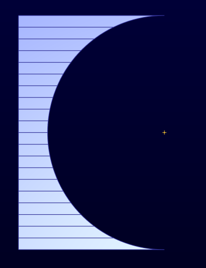
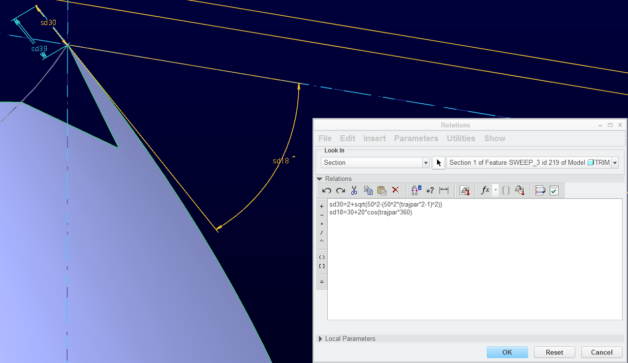
Okay, I finally got exactly what I was after; a full semicircle.
By converting the trajpar to a range from -1 to 1; and making the initial value more than 0, it works:
sd3=5-sqrt((5^2 - (((2*trajpar)-1)*5)^2))
...((2 * trajpar) - 1)... => converts the trajpar to range from -1 to 1 and the Origin for the sweep is "10" (2 * R)
So we start off with "5" - Zero (5^2=25; 2*trajpar-1=2*0-1=-1 *5=-5 ^2=25; 25-25=0 ^2=0; sqrt(0)=0; 5-0=5)
When trajpar=0 (halfway) sd3=0 ; (5^2=25; 2*trajpar-1=2*.5-1=1-1=0; 0*5=0 ^2=0;25-0=25; sqrt(25)=5; 5-5=0)
All the "5"s are the radius value and can therefore be substituted wit relations or parameters.
I find it comforting that you can have a line go to zero within the range... but not so much when you cannot define it at the beginning of the range.
Again, thanks all for helping me picture this in my mind. Somehow I was thinking I needed the sin/cos functions to get there. Had I remembered the equation Gopal originally posted, I might have been able to work it backwards from there.
Jun 21, 2013
03:36 PM
- Mark as New
- Bookmark
- Subscribe
- Mute
- Subscribe to RSS Feed
- Permalink
- Notify Moderator
Please log in to access translation
Jun 21, 2013
03:36 PM
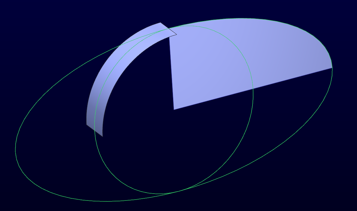
Some things just don't transfer to Creo easily. I went through 4 iterations to make this work, only to go back to the original to have it come out properly.
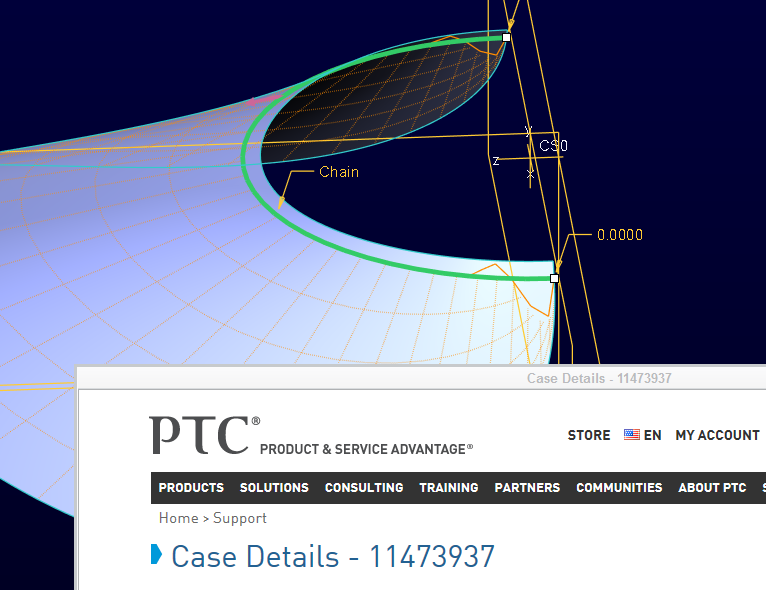
Since you cannot start out a VSS at zero, I have a tail on the swept line. The long edge is the semicircle we've been discussing. The sweep also has an angle change. Without the angle change, I could easily trim the surface with the initial sweep arc (origin), but once the angle was introduced, it failed the trim near the ends. Okay, merge? Merge failed! Revolve-remove? Failed! Merge flat sheet? Failed!
I went through several other scenarios to make this work including a half section mirror/merge and projecting the edge of a copy. They all created a small non-tangent deformation at the end.
Finally, I ended up extruding-removing a circle (arc didn't work either!) straight up through the sweep sketch. That finally did it.
Give it a try...
How can there be fewer mouse clicks when you have to do everything a half dozen times?
Jun 26, 2013
11:18 AM
- Mark as New
- Bookmark
- Subscribe
- Mute
- Subscribe to RSS Feed
- Permalink
- Notify Moderator
Please log in to access translation
Jun 26, 2013
11:18 AM
Cool stuff! I'll definately have to look at the equations, thanks!
It is the bill of a ball cap?
Jun 26, 2013
12:58 PM
- Mark as New
- Bookmark
- Subscribe
- Mute
- Subscribe to RSS Feed
- Permalink
- Notify Moderator
Please log in to access translation
Jun 26, 2013
12:58 PM
Part of a cowling...
An interesting thing happened on the way to creating this part. One that forced me to put in a CS request. When I said I had trouble trimming the "tail" from the sweep (to keep a line from starting at 0), it only fails with my config.pro. The CS didn't have an issue with my version and when we opened it with the default config.pro, it was fine. I didn't think I had anything that could cause this kind of issue with geometry integrity so when I find out, I will post it here. But I did confirm that when I imported my config.pro into the "good" session, it went stupid.
I tried a couple of setting but I didn't stumble across the offending setting. I pay PTC to resolve these so I will get back to you. It is however significant to learn this can happened.
Jun 26, 2013
01:00 PM
- Mark as New
- Bookmark
- Subscribe
- Mute
- Subscribe to RSS Feed
- Permalink
- Notify Moderator
Please log in to access translation
Jun 26, 2013
01:00 PM
Definition of "Stupid":
Jun 26, 2013
04:24 PM
- Mark as New
- Bookmark
- Subscribe
- Mute
- Subscribe to RSS Feed
- Permalink
- Notify Moderator
Please log in to access translation
Jun 26, 2013
04:24 PM
I've seen weird things like that in boundary blends near corners. IMO, Boundary blend was better and more robust before WF.
Jun 27, 2013
03:37 AM
- Mark as New
- Bookmark
- Subscribe
- Mute
- Subscribe to RSS Feed
- Permalink
- Notify Moderator
Please log in to access translation
Jun 27, 2013
03:37 AM
So far we've ruled it down to the display quality. Medium and low are fine and High and above it fails. No SPR yet, but I think one is coming since display quality really shouldn't change geometry. It is highly reproducable on this part.
Jun 27, 2013
09:45 AM
- Mark as New
- Bookmark
- Subscribe
- Mute
- Subscribe to RSS Feed
- Permalink
- Notify Moderator
Please log in to access translation
Jun 27, 2013
09:45 AM
Hmmmm, so the geometry ISN'T all weird like that? Interesting.....
Jun 27, 2013
12:34 PM
- Mark as New
- Bookmark
- Subscribe
- Mute
- Subscribe to RSS Feed
- Permalink
- Notify Moderator
Please log in to access translation
Jun 27, 2013
12:34 PM
Does it fail to create the surface on the high quality settings if you actually confirm creation of the sweep? Or will it just create distorded surface?
This is like really really odd. The boundary of that surface shouldn't change at all, while the mesh of the surface could of course with the different display quality.
Jun 27, 2013
03:21 PM
- Mark as New
- Bookmark
- Subscribe
- Mute
- Subscribe to RSS Feed
- Permalink
- Notify Moderator
Please log in to access translation
Jun 27, 2013
03:21 PM
Jakub Fojtik wrote:
Does it fail to create the surface on the high quality settings if you actually confirm creation of the sweep? Or will it just create distorded surface?
...
When you confirm, it stays that way. You can use measure on it and it shows values at the failed location. I can pick up vertexes. Oddly enough, I cannot save the measure feature.
Jakub Fojtik wrote:
...
This is like really really odd. The boundary of that surface shouldn't change at all, while the mesh of the surface could of course with the different display quality.
That is pretty much what I am saying to CS. I think I just found the perfect storm to cause this, but it explains a lot of the weird things everyone is seeing at times when working with surfaces. It really needs to be looked at carefully by PTC engineers.
I'll post up a quick video sometime today.
Jun 27, 2013
03:58 PM
- Mark as New
- Bookmark
- Subscribe
- Mute
- Subscribe to RSS Feed
- Permalink
- Notify Moderator
Please log in to access translation
Jun 27, 2013
03:58 PM
That's nasty.
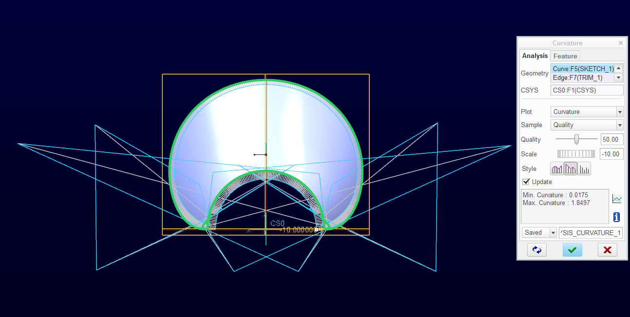
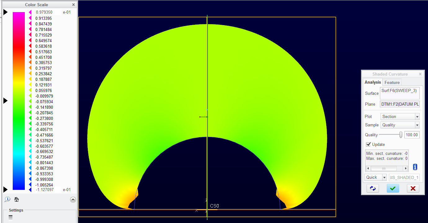
Tom, could you also please show the curvature analysis of the curves in your video? Just so one can see these are not some crazy oscilating splines, but regular curves.
Jun 27, 2013
04:17 PM
- Mark as New
- Bookmark
- Subscribe
- Mute
- Subscribe to RSS Feed
- Permalink
- Notify Moderator
Please log in to access translation
Jun 27, 2013
04:17 PM
Good idea. I will show that.
Of course it is crazy, however It has two trajpar statements. But the sweep is a simple arc.
Jun 27, 2013
05:09 PM
- Mark as New
- Bookmark
- Subscribe
- Mute
- Subscribe to RSS Feed
- Permalink
- Notify Moderator
Please log in to access translation
Jun 27, 2013
05:09 PM
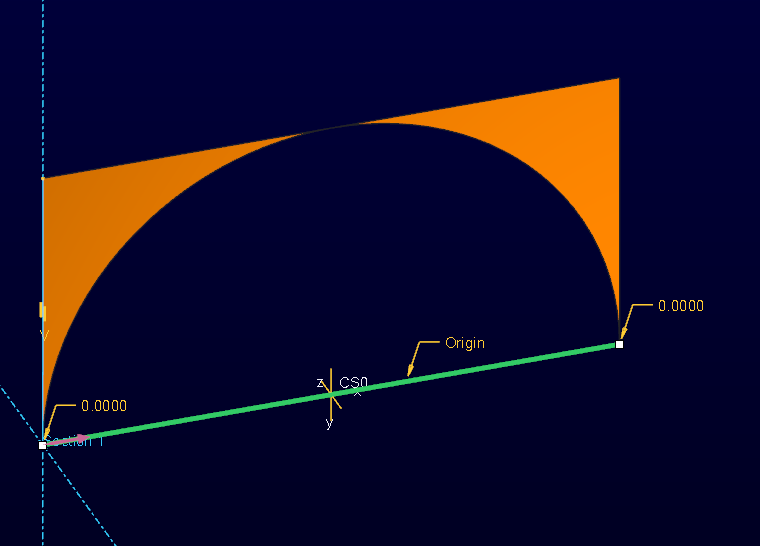
I will add the short version...
The lesson here is pay attention to the preview. It is less likely to lie than the geometry. Regardless, this feature should work and internal rounding has really corrupted the edge. Oddly enough, there is a method where this works perfectly, but it is a lot more involved. And it uses exactly the same geometry.
Jun 27, 2013
06:44 PM
- Mark as New
- Bookmark
- Subscribe
- Mute
- Subscribe to RSS Feed
- Permalink
- Notify Moderator
Please log in to access translation
Jun 27, 2013
06:44 PM
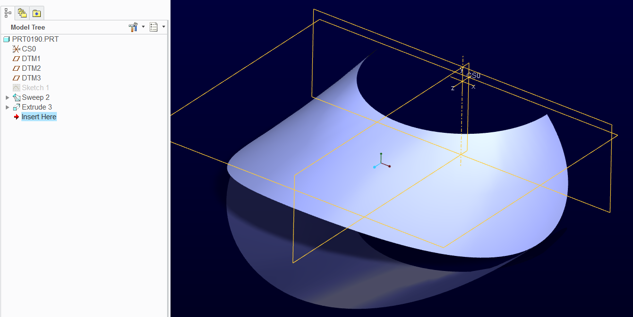
This is the solution video. Basically, I reduced the trajpar to only 1 and used the very same feature with both trajpar's for a -remove material- sweep.
Jakub, thanks for the tip on the analysis. That helped my understanding a lot.
Jun 28, 2013
12:18 PM
- Mark as New
- Bookmark
- Subscribe
- Mute
- Subscribe to RSS Feed
- Permalink
- Notify Moderator
Please log in to access translation
Jun 28, 2013
12:18 PM
You are welcome, I'm glad you got it working, and with so few features, really interesting approach.
Actually, I never knew portion of a surface can be cut out with another on-laying surface in Creo.
So, just to say again, learn something new everyday.
Jun 27, 2013
03:43 PM
- Mark as New
- Bookmark
- Subscribe
- Mute
- Subscribe to RSS Feed
- Permalink
- Notify Moderator
Please log in to access translation
Jun 27, 2013
03:43 PM
True Frank. This is an eye-opening moment!


