
Turn on suggestions
Auto-suggest helps you quickly narrow down your search results by suggesting possible matches as you type.
Showing results for
Please log in to access translation
Turn on suggestions
Auto-suggest helps you quickly narrow down your search results by suggesting possible matches as you type.
Showing results for
Community Tip - You can change your system assigned username to something more personal in your community settings. X
- Community
- Creo+ and Creo Parametric
- 3D Part & Assembly Design
- Re: Help with ProE 4.0, Custom 3D curves, .pts fil...
Translate the entire conversation x
Please log in to access translation
Options
- Subscribe to RSS Feed
- Mark Topic as New
- Mark Topic as Read
- Float this Topic for Current User
- Bookmark
- Subscribe
- Mute
- Printer Friendly Page
Help with ProE 4.0, Custom 3D curves, .pts files etc.
Jan 14, 2013
05:39 PM
- Mark as New
- Bookmark
- Subscribe
- Mute
- Subscribe to RSS Feed
- Permalink
- Notify Moderator
Please log in to access translation
Jan 14, 2013
05:39 PM
Help with ProE 4.0, Custom 3D curves, .pts files etc.
Wow.
ProE is so powerful but so frick'n not user friendly. I've attached a picture of a curve that I managed to define by projecting a sketch onto a curved surface created from another curve, The result is a nice flowy curve through 3d space, not planar. So I have my curve that I want, now I want to isolate this "curve" so I may open it up as a sketch, alone to use as the back bone for other extrusions etc. I cannot for the life of me figure out how to do this. Does this curve contain any information that I can export? Can I not save it as a seperate entity to open up as a 3D sketch? There has to be a way.....I can't imagine a CAD software as complex as ProE would not let you custom create 3D curves through intersections, projections etc. and then not let you save them............yet I can't figure it out how to isolate my custom curves.
This thread is inactive and closed by the PTC Community Management Team. If you would like to provide a reply and re-open this thread, please notify the moderator and reference the thread. You may also use "Start a topic" button to ask a new question. Please be sure to include what version of the PTC product you are using so another community member knowledgeable about your version may be able to assist.
Labels:
- Labels:
-
2D Drawing
19 REPLIES 19
Jan 14, 2013
06:42 PM
- Mark as New
- Bookmark
- Subscribe
- Mute
- Subscribe to RSS Feed
- Permalink
- Notify Moderator
Please log in to access translation
Jan 14, 2013
06:42 PM
Any curve derived like that, you can never open up in sketcher in Pro/E, or any OTHER software. Think about it: it took you 2 curves intersected with each other to make it, right? It is derived from other features, so you cannot open it in "sketcher" because it is not planar. I HATE that they're teaching Pro/E users like you're supposed to be SW users now. When you can, create all your trajectories and sections inside the feature not external (unless you're going to use them for other features). You cannot open it in sketcher but you CAN use it for sweeps etc. Of note though, sometimes you cannot do simple sweeps with these because for some stupid reason it says it's an "invalid trajectory". Bull. So, you end up having to do a VSS (Variable Section Sweep) with a constant section as it seems to have no problem with these types of trajectories. I do this kind of stuff all the time.
Jan 14, 2013
07:55 PM
- Mark as New
- Bookmark
- Subscribe
- Mute
- Subscribe to RSS Feed
- Permalink
- Notify Moderator
Please log in to access translation
Jan 14, 2013
07:55 PM
Hello Frank,
Ya, I mean that's what I thought because I spent like hours trying to comb through options to see if I could isolate this curve. But thinking about it now, you are right, sketcher only uses planar dimensions then extrusions and more comples shapes can be pulled from that. But here's the thing, I really don't understand how ProE can be so good if you can only sketch in planar form. What if I'm pulling geometry off of an organic shape that has curves that flow through 3D space...how is this done, sketching in planar to try to achieve that very precise organic shape must be a nightmare if not impossible. Basically, I'm trying to create siderails for a motorcycle frame, they are basically organic in shape, at a certain sections they curve in 3d. I also need to adhere to precise dimensions being pulled from real life, i.e motor clearance etc. I know of about 3-4 ways I could accomplish this with ProE but it's all the basic stuff, making tons of datum planes or making small parts in 2d and then welding them together. That's all easy to do, But I want to make my core lines in 3d then build off of that. What program can I do that with? I'll save proe for smaller 2d parts like brackets, mounts etc.
I understand I could also use the CurveID's to build from while in part mode but there are usually referencing surfaces associated with their creation that get in the way, I just want a nice simple, accurately measured 3D line to sculpt from.
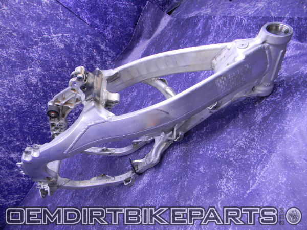
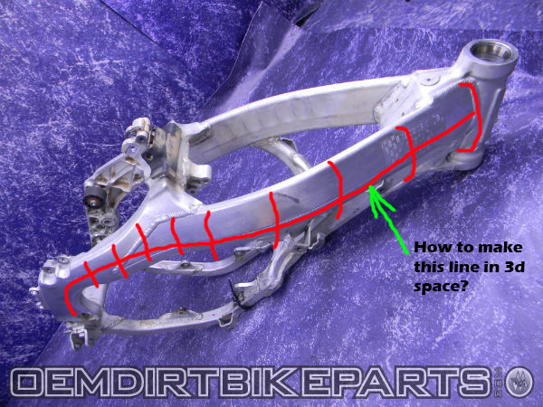
If you look at the picture I've attached, I'm trying to make lines for the main "side rails" or perimeter beams in the frame similar to that of a CR125 dirtbike. Starting from the bottom they move up, fairly flat but then dip in for leg clearance and buldge back out where the gas tank sits, Very organic and shaply. I need to be able to draw lines that will let me build a similar geometry, but very accurately to measured spec. I know that if I could get atleast two main 3d trajectory lines in there, I could build a chain, although difficult to form most the rail by doing a boundary blend. But I can't figure out how to make these first two initial lines through 3D space. I can't just throw it into "styling" to stretch and pull a 2D sketch, it needs to be sketched with accuracy. Any tips, suggestions?
Jan 14, 2013
08:06 PM
- Mark as New
- Bookmark
- Subscribe
- Mute
- Subscribe to RSS Feed
- Permalink
- Notify Moderator
Please log in to access translation
Jan 14, 2013
08:06 PM
I've started playing around with .pts files and I'm thinking that this is most likely the route i'll have to go.....BUT.
What the heck is the point! CAD is supposed to make life easier! even if I go with .pts files, I need some way of controlling and visuallising the coords in order to get the right dimensions of my curve etc.You should be able to work backwards, ie, draw your curve, dimension it and then extract the raw coords into a file, or better yet just be able to save the Curve right from software interface. Something is fishy here. There is something I'm missing. I would think this would be the backbone of CAD software.No?
Jan 23, 2013
06:01 PM
- Mark as New
- Bookmark
- Subscribe
- Mute
- Subscribe to RSS Feed
- Permalink
- Notify Moderator
Please log in to access translation
Jan 23, 2013
06:01 PM
The thing is, is that in ANY sketching mode, in any software I know of, you're limited to 2D. Trust me, it would be extremely tough to even try and get what you want if you had a true 3D sketcher. You'd try and bend a curve in the viewing orientation you were in, then rotate it and realize you'd done something you didn't want. Honestly, that's the way it has to be done to get what you want. There are some freeform tools in Pro/E for modifying surfaces, try them and you'll see what I mean.
Jan 28, 2013
04:12 PM
- Mark as New
- Bookmark
- Subscribe
- Mute
- Subscribe to RSS Feed
- Permalink
- Notify Moderator
Please log in to access translation
Jan 28, 2013
04:12 PM
Hi Frank,
Ok, well, if creating a 3D curve is not possible then how do we have all these products with organic shapes out there in the world. The companies making these products must have had to adhere to certain measurements and tolerances when designing there parts, so they couldn't have just used the free-form tool, which I find is kind of a pointless tool if tolerances can't be seen. You're just supposed to stretch your part until it "looks" about right...?
There is an option that let's you INTERSECT two lines sketched on two different planes and will create a line that is the mean of the two which essentially is like making a 3d curve. I think this is the route I will take, I've been practicing with this method with some success, and it seems to be the only way to make a line(based on dimensioning) to flow through 3D space.
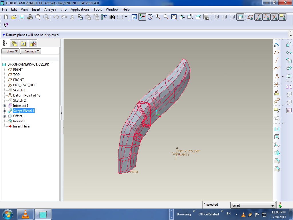
So now, If I take this 3D intersect line, I can then make it into a trajectory line and create a swept blend(consisting of multiple sketches along it) to make the side rail part of the frame( the part that I have outlined in red in the picture above) It's looking like it's the only method to get the shape that I want. What does everyone think, would they approach it differently?
Cheers
Jan 28, 2013
04:57 PM
- Mark as New
- Bookmark
- Subscribe
- Mute
- Subscribe to RSS Feed
- Permalink
- Notify Moderator
Please log in to access translation
Jan 28, 2013
04:57 PM
Actually, free-form is exactly what most of those Industrial Design tools do. you push and pull, but then you generally will take that into another software, like Pro/E, and add your bosses, parting lines, draft, reveals, etc.
Like I said, play with the Warp feature to see what I mean about being impossible to actually sketch in 3D. You're ALWAYS in 2D, you just keep rotating things in 3D, and changing them again in 2D. For instance, mouses, or trackballs, are ONLY 2D devices for input. you can move the plane around, but it will still always be only 2D.
Any kind (almost, anyways) of 3D curve can be done as the intersection of 2, 2D curves. Be careful though, that feature seems to have lost some of it's accuracy. I' ve had to intersect 2 surfaces to create an accurate curve because just interseting 2 curves it didn't come out correctly like it USED to before they changed things in WF4.
Jan 28, 2013
11:11 PM
- Mark as New
- Bookmark
- Subscribe
- Mute
- Subscribe to RSS Feed
- Permalink
- Notify Moderator
Please log in to access translation
Jan 28, 2013
11:11 PM
So how would you go about designing the frame in the pictures above? Or atleast the side pillars which I highlighted in red.....I'm sure I can get close to what I want using a swept blend on an Curved(intersection) tradjectory line. I've practiced with this method and it gives me the rudimentary shape I'm looking for.
My idea was to do it in about 5 parts, then assemble them together. The assembly joints would be the "weld" lines. The side pillars(do one then mirror it), maybe a front head tube section, the shock tower(which is the part sticking up in the middle of the frame) and the lower motor mounts, and then the two tubes that cradle the motor. This is a Honda frame and it looks like it was made with CAD so it should be able to be replicated.....
Jan 28, 2013
11:19 PM
- Mark as New
- Bookmark
- Subscribe
- Mute
- Subscribe to RSS Feed
- Permalink
- Notify Moderator
Please log in to access translation
Jan 28, 2013
11:19 PM
Do you have the frame in CAD already? This is actually pretty easy with an Offset onto the surface.
This command allows you create a 2D sketch on a plane, but the feature is projected onto the curved surface and the thickness is applied to the selected face for a consistent thickness. Pretty cool!
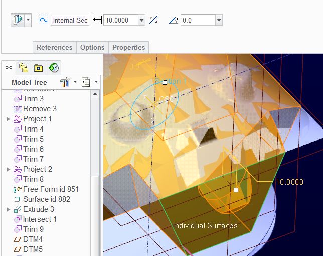
The attached is a Creo 2.0 version of the part file roughly similar to the OP's request...
Jan 29, 2013
12:32 AM
- Mark as New
- Bookmark
- Subscribe
- Mute
- Subscribe to RSS Feed
- Permalink
- Notify Moderator
Please log in to access translation
Jan 29, 2013
12:32 AM
Hi Tom!
Great to get some more input from others aswell! No, no part file, otherwise I would use it as referrence but if you search CR125 frame on google, there are plenty of pictures and references to base a design plan. I like Honda's frame design, the split frame concept, and I'm using their design as the basis for my own. Hopefully if I ever produce any I won't run into patent issues )
Anyhoo.
Oh ofcourse, I'm familiar with the offset option, but think about it, you need to first create the curved surface on which to throw the offset sketch. I will definately need to use this feature later as I will need to "carve" out pockets through out the siderails for weight reduction etc. If you notice in the pictures of the frame above, on the inside of the lower part of the siderails, it's pocketed for weight reduction. That's a perfect candidate for the offset feature. The part is probably die cast or sand cast. Atleast that lower section.
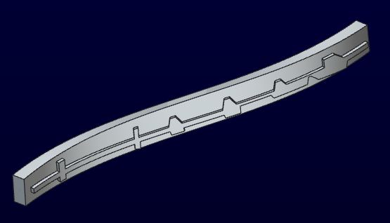
You see, I'm really leaning towards sculpting the side rails using a swept blend along a tradjectory line, hopefully it will give me enough control in creating the shape of the entire siderail, the part thickens in area's, changes shape and dimension, it's really complicated but not impossible, with each sketch I can tweak the shape and keep dimensions accurate. I'll plan to have perhaps 20 or so sketches for the whole rail, positioned about every 2" along the trajectory line. Does anyone see any complications with this? suggestions?
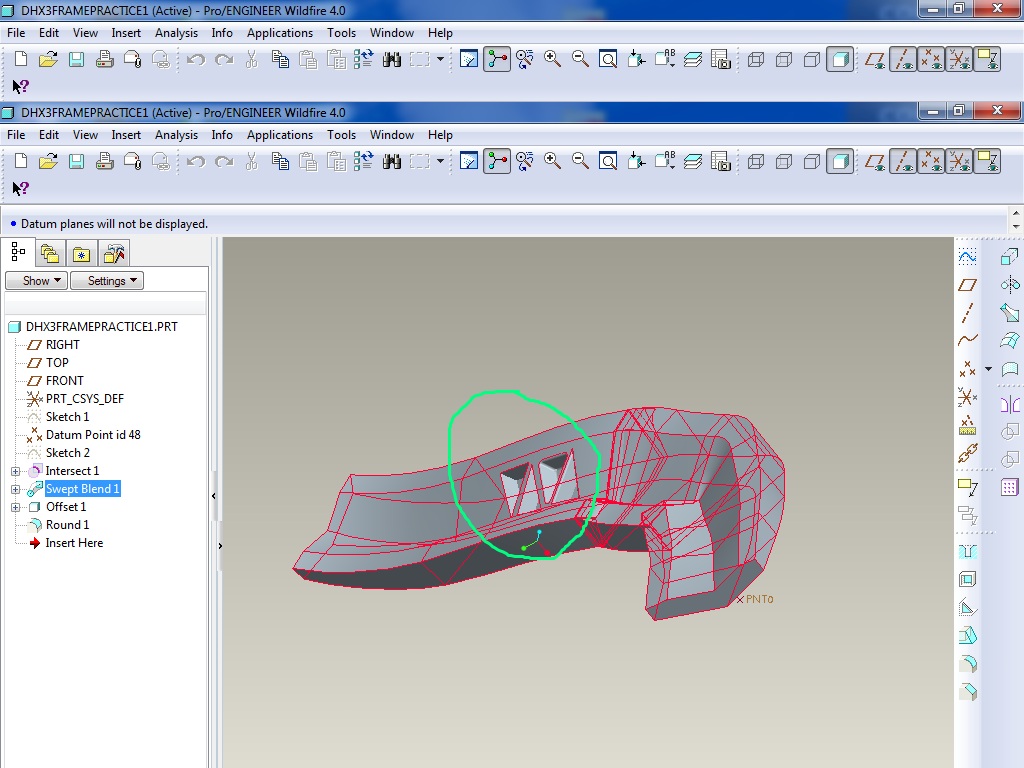
Here's a very rough example of how far I've come with this method. Keep in mind, the sketches I used were just rediculously quick hidious things just to prove concept and see what kind of shapes came out. I think there are about 4 sketches in total, about 10 entities each. I was even able to experiment with offset to make pocketing (circled in green). Again, just proving concepts at the moment and pre-thinking the design steps...
the more feedback, the better!
Jan 29, 2013
12:54 AM
- Mark as New
- Bookmark
- Subscribe
- Mute
- Subscribe to RSS Feed
- Permalink
- Notify Moderator
Please log in to access translation
Jan 29, 2013
12:54 AM
Well, the original is a pair of bars welded into a casting on either end. I was thinking you were trying to add ribs to the original. Now I understand what you are trying to do. I might suggest following their original idea and making each of the parts separate and assembling them for a weldment. They are using as much bent raw flatstock as possible to connect the heavily features castings. Changing that barstock to castings is bolt.
I just went through one of these and used photo's minimizing perspective by zooming into the actual part from far away. To do what you are trying to do, I might be on the lookout for a 3D inspection scanner.
Jan 29, 2013
01:45 AM
- Mark as New
- Bookmark
- Subscribe
- Mute
- Subscribe to RSS Feed
- Permalink
- Notify Moderator
Please log in to access translation
Jan 29, 2013
01:45 AM
No, I wasn't trying to add ribs, the red lines were just to show how one could make defining sketches along a trajectory line to "sweep blend" the shape of the two side rails...
For sure, basically I'd like to split that main side rail into 2 parts, just like they have done. A lower casted part and that flat tube section bent section, however, In my design though, I was thinking of using a pocketed casted section, similar to the lower section instead of the bent tubing, so essentially the whole rail would be "cast". Just seems like it would be easier and cheaper to make than that intricately shaped flat tubing section, with regards to final manufacturing process. Those flat tubes are probably hydro formed, it's very expensive.
a 3D inspection scanner is the way to go these days, kinda pricey though. I wonder what kind of data can be used from the scan? it would be nice to able to import a scan into ProE and then manipulate it. Regardless of scanner, It can totally be done in software....learning with every post.
Jan 29, 2013
01:54 AM
- Mark as New
- Bookmark
- Subscribe
- Mute
- Subscribe to RSS Feed
- Permalink
- Notify Moderator
Please log in to access translation
Jan 29, 2013
01:54 AM
Would there be a way to build the full side rail part then somehow "cut it" into two seperate parts? saving each part as it's own part file? Or do you have to plan ahead. Aren't there options to build a part while you are assembly mode, that would let you build off of an existing goemetry etc. I have zero hours with assembly mode.
I would cut the rail into 2 pieces exaclty where it is welded in the picture above.
Jan 29, 2013
01:14 PM
- Mark as New
- Bookmark
- Subscribe
- Mute
- Subscribe to RSS Feed
- Permalink
- Notify Moderator
Please log in to access translation
Jan 29, 2013
01:14 PM
Without the frame in hand, I couldn't tell you the exact method I'd use. I WOULD for sure do it as a top-down model, so that I could use the surfaces and curves I'd create at the top assembly to control all the pieces to be made by different methods.
Just from a quick glance at the small pic, the sides don't look hydroformed to me. You'd only use hydroforming if the section itself changed along a swept trajectory, or if there were pockets etc. If the section remains the same, you can simply extrude the tube, and bend it. I see some weird oval shaped marks on the inside of the far frame spar. As small as the pic is, I can't tell if the "tube" is an open-section piece of sheetmetal that's then welded shut or not.
For the side plates, they look like die-castings to me. Die-castings will have ejector-pin marks (small circular marks), a parting line, usually be more complicated, and have a much smoother surface finish. Sand castings will have no ejector pin marks, are usually larger and heavier, and have a rougher, sand-blasted appearance (unless they've been cleaned up).
You can copy anything you want without patent issues, you can not SELL a copy without patent issues without risk of repercussion. And that's only IF any part of that frame is patented (doubt it).
Scanned in objects are usually extremely dense point clouds, i.e. without software that will automatically produce surfaces from it, it's a PAIN to deal with. And, even if it does produce surfaces, they're usually very pockmarked and rippled. Uck!
Jan 29, 2013
02:11 PM
- Mark as New
- Bookmark
- Subscribe
- Mute
- Subscribe to RSS Feed
- Permalink
- Notify Moderator
Please log in to access translation
Jan 29, 2013
02:11 PM
Upon second look, those side spares could have been extruded yes. The oval shadows on the inside of the spare are bend pleats. They probably extrude the flattened oval tube, then machine bend it to shape and cut the notches out to fit with the side plates head tube etc. All the effect I'm going for. It's a very elegantly designed frame, probably the nicest in the offroad industry atm, very few are doing twin spare and when you study it's design, you see how much thought had to go into making it.
Jan 29, 2013
03:01 PM
- Mark as New
- Bookmark
- Subscribe
- Mute
- Subscribe to RSS Feed
- Permalink
- Notify Moderator
Please log in to access translation
Jan 29, 2013
03:01 PM
I'm almost sure that the full profile of the tube is set into the casting and then welded along the common edge.
Yes, the 3D scanning tools create point clouds. Some included software will do a crude IGES approximations. Certainly good enough for an underlay.
Frank is right. These kinds of "copy" designs are almost always done top down. The idea, even in the original design, is that you create an "interface" model. A location that manages all the critical interfaces with other parts for the assembly. From that, you can sculpt your frame around it.
You can save a mirror image of any part file.
Jan 29, 2013
03:10 PM
- Mark as New
- Bookmark
- Subscribe
- Mute
- Subscribe to RSS Feed
- Permalink
- Notify Moderator
Please log in to access translation
Jan 29, 2013
03:10 PM
"Top down"? I'm not sure I understand the concept? Do you mean you would start by making sketches using the top plane looking down onto the frame? and extrude? Can you show a print screen of what you mean?
"interface model"? By this you mean to have a rough set of shapes and dimensions to build all the parts in assembly mode? Kind of like a bike frame building jig?
Jan 29, 2013
03:31 PM
- Mark as New
- Bookmark
- Subscribe
- Mute
- Subscribe to RSS Feed
- Permalink
- Notify Moderator
Please log in to access translation
Jan 29, 2013
03:31 PM
Top down means you can reference features in your assembly to create your model. And yes, a sort of skeleton that you can use for references in your piece parts.
When you have -say- 3 parts in an assembly and you click on one of the parts (try the last one as it is order dependent) and select Activate. You are now editing the part, not the assembly. Create a new sketch and create dimensions to a different part in the assembly. That "part" sketch is now dependant on the assembly.
of course, this can get you in a whole lot of trouble too  Many companies have policies forbidding this kind of practice. But properly done, it can be a really powerful tool.
Jan 29, 2013
03:42 PM
- Mark as New
- Bookmark
- Subscribe
- Mute
- Subscribe to RSS Feed
- Permalink
- Notify Moderator
Please log in to access translation
Jan 29, 2013
03:42 PM
Step-by-step explanation of Top-Down design by Brian can be found here:
Jan 29, 2013
04:43 PM
- Mark as New
- Bookmark
- Subscribe
- Mute
- Subscribe to RSS Feed
- Permalink
- Notify Moderator
Please log in to access translation
Jan 29, 2013
04:43 PM
Jakub, really appreciate the link. Very relative to what I'm trying do, the example is even a motorcycle frame, only it's tubular but the concepts are similar....helps alot. thanks.


