1-Visitor
September 15, 2015
Question

Hole table in drawing

  • September 15, 2015
  • 1 reply
  • 3717 views

Helo,

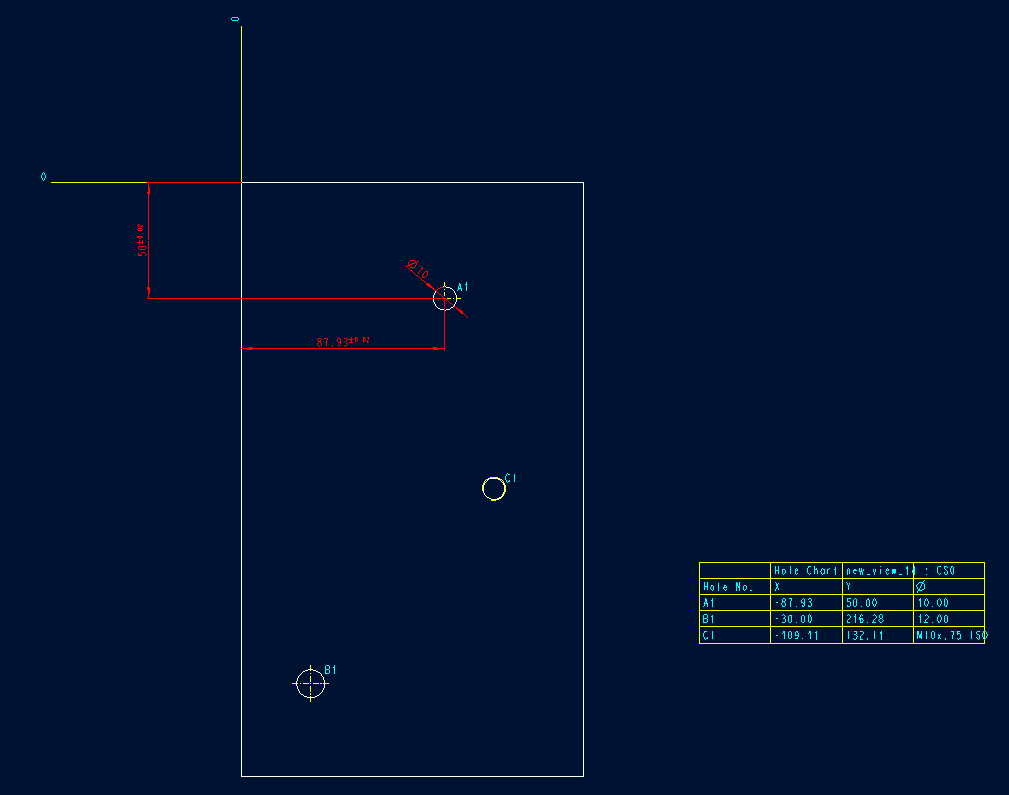
I am trying to use hole tables in drawing instead of coordinates and cannot find how to show hole tolerances (for ex. H7) and position tolerances (+-0.02). Is ther some way how to show both in the hole table?


Screenshot_4.png


Thanks in advance. T.


This thread is inactive and closed by the PTC Community Management Team. If you would like to provide a reply and re-open this thread, please notify the moderator and reference the thread. You may also use "Start a topic" button to ask a new question. Please be sure to include what version of the PTC product you are using so another community member knowledgeable about your version may be able to assist.

1 reply

12-Amethyst
September 15, 2015

shown with WF4

Holes were placed with existing tables and were assigned tolerances.

Dimensions were also adjusted and toleranced accordingly.

This information is carried into the tables as such:

1pic.png

then switch your dimensions (info > switch dims)

2pic.png

Put these values (only "&d<value>") in your chart, like so:

3pic.png

notes are a bit different, but not too much, get the name from your model tree

4pic.png

I think that answers your question.

thlavinka1-VisitorAuthor
1-Visitor
September 15, 2015

Hi Ron,

I think I did not explain the problem exactly (I am sorry for my english) but I am just trying to find some easier way to make drawings that include many holes - it just takes long time and so on.

Here is one example:

Screenshot_3.png

so far i was just dimensioning all holes by coordinates. Now i noticed there exists a functionality called "hole table". The table is very easy and fast to make but there are two things i would need to add in it: a hole tolerance and a hole position tolerance.

12-Amethyst
September 15, 2015

For ISO standard models, you may want to investigate the use of tolerance tables.

It looks to be a little involved (with all the class types) but may be what you are looking for regarding "automatic" tolerancing of hole/shaft fits.

look here Tutorial: Support for Tolerance Tables for ISO Models

Putting this creo assigned variable name into a charted table differently from what I've shown is beyond my capabilities at this point.  I've never had a need.

I'm sure it can be done, but I can not provide the solution (yet).  Perhaps another user can help.

ron