Community Tip - Your Friends List is a way to easily have access to the community members that you interact with the most! X
- Community
- Creo+ and Creo Parametric
- 3D Part & Assembly Design
- Re: How can i do it?
- Subscribe to RSS Feed
- Mark Topic as New
- Mark Topic as Read
- Float this Topic for Current User
- Bookmark
- Subscribe
- Mute
- Printer Friendly Page
How can i do it?
- Mark as New
- Bookmark
- Subscribe
- Mute
- Subscribe to RSS Feed
- Permalink
- Notify Moderator
How can i do it?

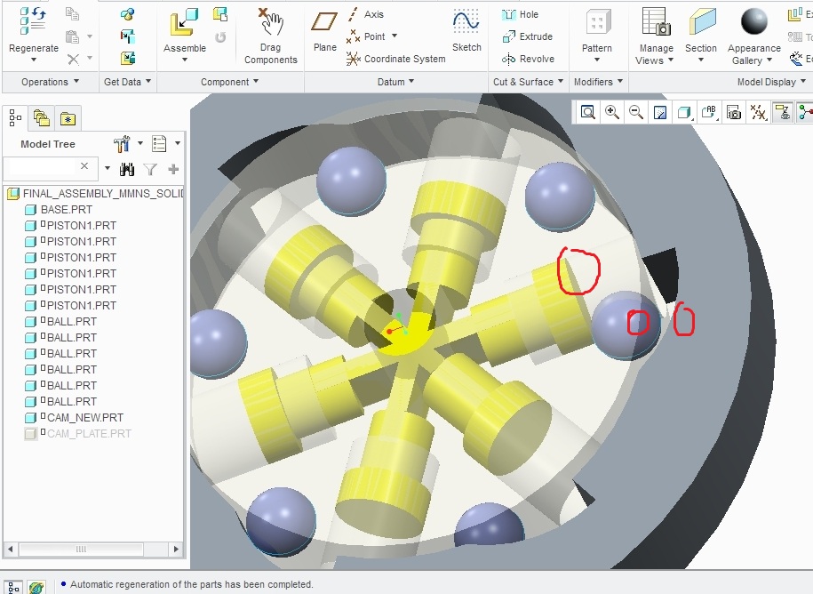
The problem is how to assemble the piston, the ball and the circular CAM ring ?
The working seems so simple : u rotate the CAM ring anti-CW to a degree, it pushes the ball and the ball pushes the plunger/piston...punching done...
Can someone help me out?
- Mark as New
- Bookmark
- Subscribe
- Mute
- Subscribe to RSS Feed
- Permalink
- Notify Moderator
We often add features to make sure we have things we can contrain.
In the case of the sphere and piston, tangency and axis; in the case of the cam, tangency or follow a curve path.
If you want to share the model, we might be able to come up with something slicker.
- Mark as New
- Bookmark
- Subscribe
- Mute
- Subscribe to RSS Feed
- Permalink
- Notify Moderator
Sir,
I have added the files.Please correct them if you can and re-attach them again so i could see where i was wrong.
Also, can you give me any feedback regarding how i should learn the MECHANISM and MECHANICA.
Since, i am in a college i can opt for "PTC 1 year e-Learning licence for Creo pararmetric"....
Should i buy that for learning the Advanced CREO applications....?
Is there any book available that covers MECHANISM and MECHANICA both...?
Thanking You,
Anshul Singh
Under-Graduate Student
Mechanical and Automation Engineering
- Mark as New
- Bookmark
- Subscribe
- Mute
- Subscribe to RSS Feed
- Permalink
- Notify Moderator
I will have a look later today on the assembly.
As for Mechanism, cool feature but I am no expert at it. It is extra work that I am not sure is useful in most of my efforts but I can see occasion to use it, so I do need to learn it better. It is highly effective if motion is a key element in your day to day work.
I do remember taking some helpful tutorials on this with the e-learning module. For some reason, it is not part of my current e-learning license. I have found some helpful You-Tube videos on it however. I am still having trouble just setting up the motor ![]()
I try to stay within the bound of the basic package but I can see how it can quickly fall into shortcomings with plastics design and maybe even some highly dynamic assembly models. Then again, I am old world... I can develop an entire system with non-parametric wireframe modelers and be perfectly happy. So do not use me as an example. It is always good to learn as much as you can about the software you are using. Knowing its capabilities is -as- important as using it.
- Mark as New
- Bookmark
- Subscribe
- Mute
- Subscribe to RSS Feed
- Permalink
- Notify Moderator
Attached is the file with a single piston/ball contrained. I moved the cam to the front and gave it an angle contraint. This angle can be varied for seeing the motion. Not like mechanism, but it does change the piston as the cam changes. It can be driven to error once you exceed the contraints.
Mechanism can do a much better job as it adds contraint limits to the cam. Also note that the piston is shown with degrees of freedom although it lists as fully contrained. It is the ball that says it is partially contrained yet nothing can move. PTC still has some work to do here. But the ball/piston is contrained and will follow the cam between 38.5 and 54 degrees.
In this case, I used the simple tangent contraint and alighned axis. Also controlling orientation with planes, which is good to do. Normally, radial components will allow loose rotational contraints to be considered "assumed" contrained.
I've never tried zipping up a complete assembly, so I hope it came out correctly. Creo 2.0 M020.


