
Turn on suggestions
Auto-suggest helps you quickly narrow down your search results by suggesting possible matches as you type.
Showing results for
Please log in to access translation
Turn on suggestions
Auto-suggest helps you quickly narrow down your search results by suggesting possible matches as you type.
Showing results for
Community Tip - Visit the PTCooler (the community lounge) to get to know your fellow community members and check out some of Dale's Friday Humor posts! X
- Community
- Creo+ and Creo Parametric
- 3D Part & Assembly Design
- How do I add this dimension
Translate the entire conversation x
Please log in to access translation
Options
- Subscribe to RSS Feed
- Mark Topic as New
- Mark Topic as Read
- Float this Topic for Current User
- Bookmark
- Subscribe
- Mute
- Printer Friendly Page
How do I add this dimension
Apr 10, 2014
05:27 AM
- Mark as New
- Bookmark
- Subscribe
- Mute
- Subscribe to RSS Feed
- Permalink
- Notify Moderator
Please log in to access translation
Apr 10, 2014
05:27 AM
How do I add this dimension
Hi
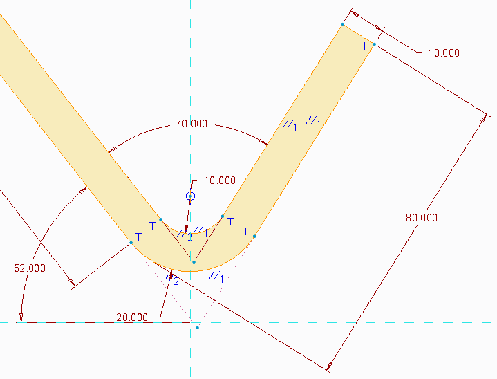
I am trying to dimension a drawing.
I want to dimension the upper bend as I did on the lower bend (20,3), see picture.
I want the dimension to be from the end of the bend to the outer tangent of the bend radius (outer).
The dimension shall be slanted along the direction of the bend.
In SolidWorks you just selected the end line of the bend and the radius.
Right click-select max dimension.
I don´t know how to make this in creo.
This thread is inactive and closed by the PTC Community Management Team. If you would like to provide a reply and re-open this thread, please notify the moderator and reference the thread. You may also use "Start a topic" button to ask a new question. Please be sure to include what version of the PTC product you are using so another community member knowledgeable about your version may be able to assist.
Labels:
- Labels:
-
2D Drawing
7 REPLIES 7
Apr 10, 2014
06:09 AM
- Mark as New
- Bookmark
- Subscribe
- Mute
- Subscribe to RSS Feed
- Permalink
- Notify Moderator
Please log in to access translation
Apr 10, 2014
06:09 AM
you may need to create draft entities..I guess
Apr 10, 2014
07:07 AM
- Mark as New
- Bookmark
- Subscribe
- Mute
- Subscribe to RSS Feed
- Permalink
- Notify Moderator
Please log in to access translation
Apr 10, 2014
07:07 AM
I´m not sure about what you mean?
Apr 10, 2014
07:24 AM
- Mark as New
- Bookmark
- Subscribe
- Mute
- Subscribe to RSS Feed
- Permalink
- Notify Moderator
Please log in to access translation
Apr 10, 2014
07:24 AM
Is that dimension to the intersect points? If so, then
(1) Change the "attach type" to "Intersect"
(2) Pick the points by picking the first entity then holding the CTRL button while picking the second
(3) Hit the middle mouse button to place the dimension. It will ask you what the orientation should be. Pick "Parallel", then select the line you want the dimension to be aligned with.
Hopefully I'm not oversimplifying your needs.
Apr 10, 2014
07:28 AM
- Mark as New
- Bookmark
- Subscribe
- Mute
- Subscribe to RSS Feed
- Permalink
- Notify Moderator
Please log in to access translation
Apr 10, 2014
07:28 AM
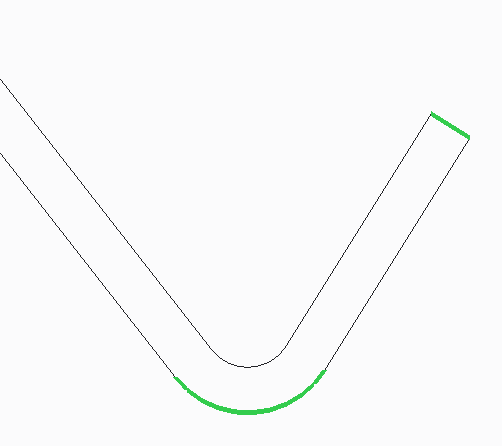
No it´s not the intersect points.
I want the dimension to be to the maximum distance of the arc (tangent) parallell to the bend.
Apr 10, 2014
07:31 AM
- Mark as New
- Bookmark
- Subscribe
- Mute
- Subscribe to RSS Feed
- Permalink
- Notify Moderator
Please log in to access translation
Apr 10, 2014
07:31 AM
go to sketch tab and create draft create some extended intersection points, then you may dimension it?
Apr 10, 2014
11:57 AM
- Mark as New
- Bookmark
- Subscribe
- Mute
- Subscribe to RSS Feed
- Permalink
- Notify Moderator
Please log in to access translation
Apr 10, 2014
11:57 AM
You might want to have the dimension go to the two tangents of the bend radius, but the programmer for the part is going to interpret this as intersect on the bottom half unless you spell this out specifically. Never leave ambiguity on a drawing.
However, the way you can manage odd drafting requirements is to put the feature in the model. In this case, you can make an associative sketch in the model on a hidden layer where you have the dimension you want (as a reference dimension). Once you show the dimension in the drawing, you can remove the reference and format the dimension however you want.
Nov 24, 2014
12:26 PM
- Mark as New
- Bookmark
- Subscribe
- Mute
- Subscribe to RSS Feed
- Permalink
- Notify Moderator
Please log in to access translation
Nov 24, 2014
12:26 PM
To avoid ambiguity, use detail views and increase scale to clearly show the dimension is to the tangency and not to the intersection point.
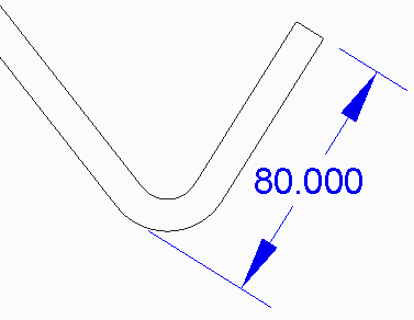
In Creo 2.0, you have at least two options to get what you want. I used a simple extrusion to illustrate. I don't know how you created your geometry and I haven't used the Sheet Metal package to know if this works there.
1. In your model sketch, pick the end of the bend leg and the bend arc and right click to locate the dimension. It doesn't seem to make a difference where you pick on the arc. The dimension will be to the arc tangent. (See the 80.000 dimension in the picture.)
Then, on your drawing, use Show Model Annotations to display the dimension.
2. If you modeled differntly and need to create the dimension on the drawing, select On Entity for dimension attachment type and pick the end of the bend leg and the bend arc.
Then, middle click to accept and select Tangent for arc pnt type.
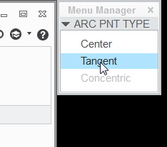
The dimension is placed.


