Community Tip - You can subscribe to a forum, label or individual post and receive email notifications when someone posts a new topic or reply. Learn more! X
- Community
- Creo+ and Creo Parametric
- 3D Part & Assembly Design
- Re: How to Extrude Wrapped Text
- Subscribe to RSS Feed
- Mark Topic as New
- Mark Topic as Read
- Float this Topic for Current User
- Bookmark
- Subscribe
- Mute
- Printer Friendly Page
How to Extrude Wrapped Text
- Mark as New
- Bookmark
- Subscribe
- Mute
- Subscribe to RSS Feed
- Permalink
- Notify Moderator
How to Extrude Wrapped Text
I have read MANY articles/posts and watched many video's on this topic and I am still not able to figure it out (which is sad).
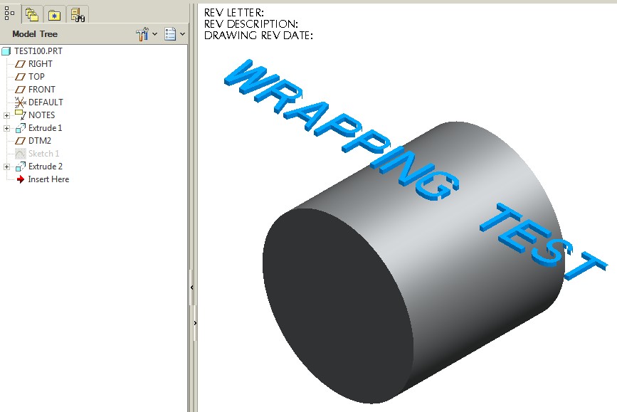
I have some text which is wrapped around a cylinder more than 180 degree's (see image below).
I have read that I need to create an offset surface and project my text onto this offset surface...the problem is that the text wraps around the entire cylinder. I can NOT project all the wrapped text on an offset sketch plane (does this make sense?).
Here is a very boiled down image of what I would like to wrap/extrude:
Solved! Go to Solution.
Accepted Solutions
- Mark as New
- Bookmark
- Subscribe
- Mute
- Subscribe to RSS Feed
- Permalink
- Notify Moderator
The Following is a quick guide on how to wrap 'text' around a cylinder 360 degree's.
I received help from Antonius and Frank on this process.
I am sure there are other ways to skin this cat but this works for me (I hope this helps someone out).
Step #1: Create Datum Plane Tangent to cylinder.
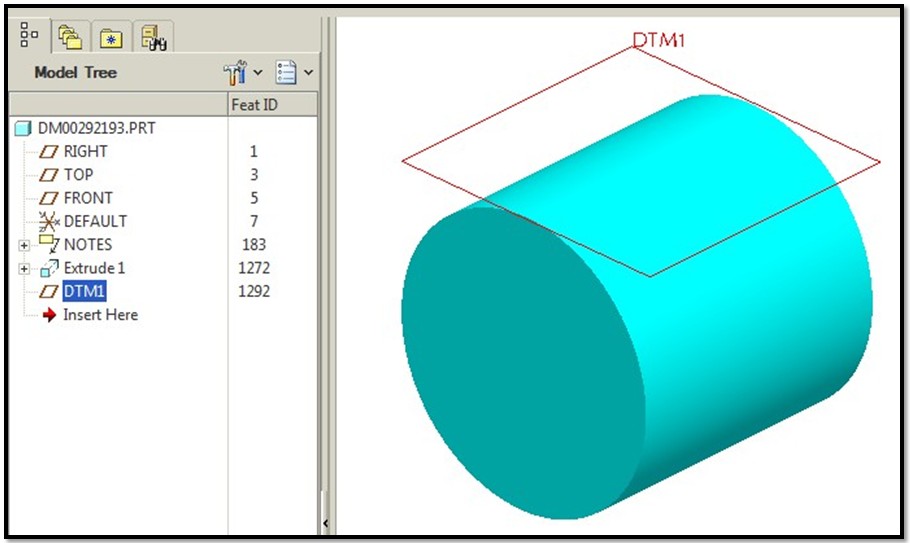
Step #2: Sketch 'Text' on Datum Plane.
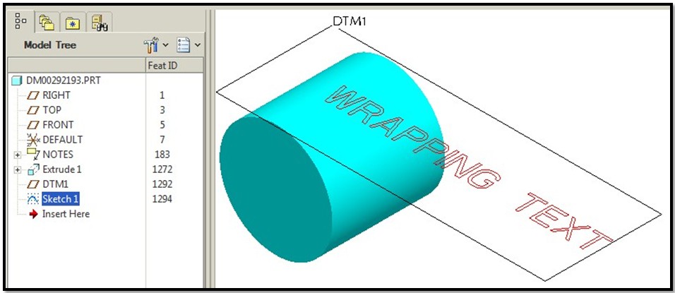
Step #3: Create a 'Designated Area' out of the 'text':
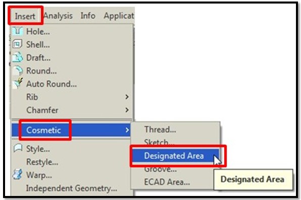
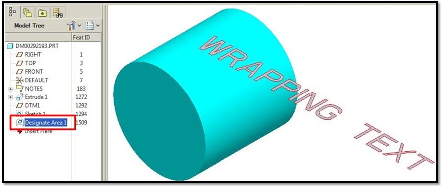
Step #4: Prepare for Spinal Bend by Creating the following:
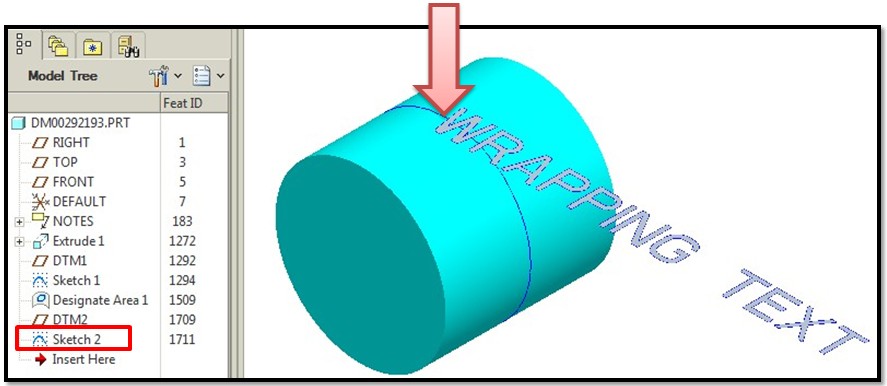
- Step #4a: Create Bend Trajectory Sketch as shown below (in this example...create a circle and divide it at the tangent point assoicated to the Datum Plane in Step #1)
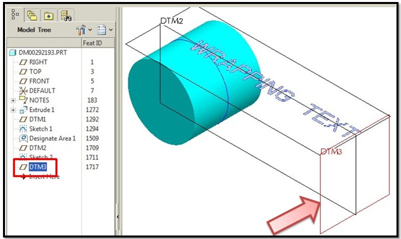
- Step #4b: Create datum plane located at the end of the 'text' as shown:
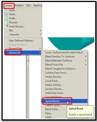
Step #5: Create a 'Spinal Bend' of the 'text'.
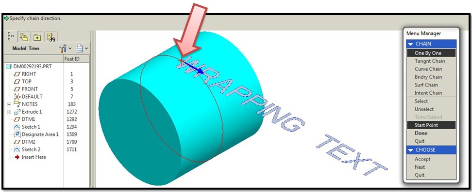
- Besure to pick the correct starting point (as shown below):
- Here is what the 'spinal bend' feature looks like (as shown below):
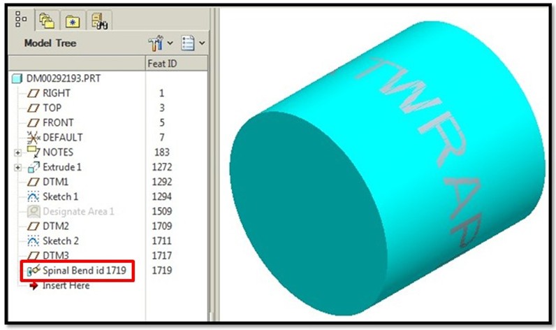
Step #6: Final Step....'Thicken' the 'Spinal Bend' feature.....
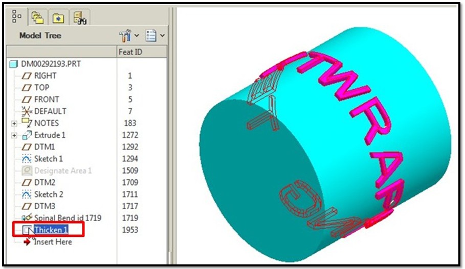
Again, I am sure there is more than one way to do this (and I wish PTC would just let us extrude a wrapped sketch....but at the moment we can not...are you listening PTC??)
I hope this helps someone. Goodluck!!!
Thanks again to Antonius and Frank for their help!!
-Kevin
- Mark as New
- Bookmark
- Subscribe
- Mute
- Subscribe to RSS Feed
- Permalink
- Notify Moderator
It can be done and you have to play with it.
The idea in this case is that you wrap the text as you have done.
You cannot project a sketch with "text" in the sketch. You have to "offset" the curves of text.
In your case, you would do maybe 4 offsets, one at every 90 degrees (maybe 120x3).
Offset is the way you create a raised area on a curved surface. In this case, you wrap the text onto the cylinder and you "project" it back to a flat plane (now distorted and squished). You then Offset these distorted sketches onto the surface.
Are you using the full version of Creo 2.0 parametric?
- Mark as New
- Bookmark
- Subscribe
- Mute
- Subscribe to RSS Feed
- Permalink
- Notify Moderator
I am using WF5.
I did read somewhere that I might have to project 'multiple' sections of my text because it wraps around the cylinder....this just seem crazy to me.
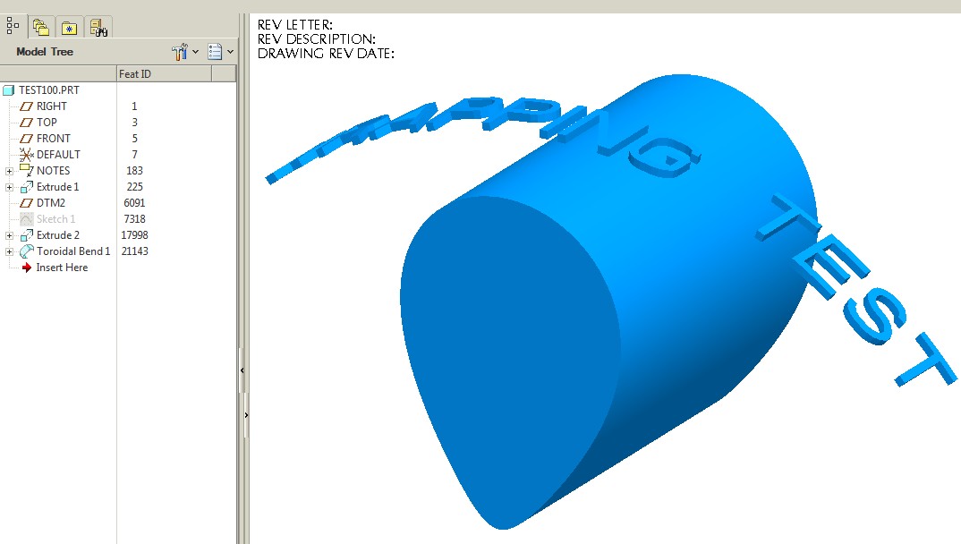
I also tried using the 'Torodial Bend' command (see images below). I was successful in bending just a sketch and extrude but NOT successfuly when trying to bend text around a cylinder.
I guess I was hoping for something simple and not have to do 4 offsets (or maybe 3 offsets at 120 degs) like you suggested.
I think I read that 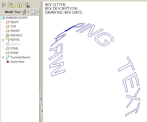
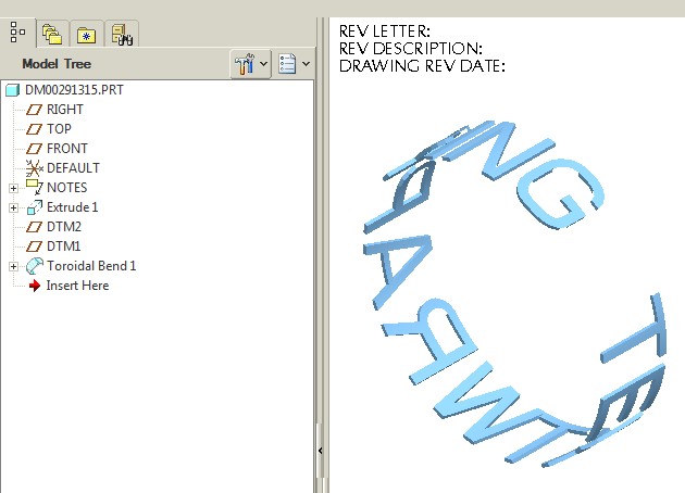
- Mark as New
- Bookmark
- Subscribe
- Mute
- Subscribe to RSS Feed
- Permalink
- Notify Moderator
I have not found a better way to manage consistent offsets from curved surfaces. And there are options with the offset feature. Not sure what limitations WF5 adds, but in general, things are not any easier in Creo.
Spinal bends can work if the plane only distorts in one direction. Careful control over the spinal bend feature will remove distortion and properly wrap as expected.
This text wrapped more than 360 degrees.
- Mark as New
- Bookmark
- Subscribe
- Mute
- Subscribe to RSS Feed
- Permalink
- Notify Moderator
I see you are using toroidal bend in your samples. Spinal bends may be a little simpler.
- Mark as New
- Bookmark
- Subscribe
- Mute
- Subscribe to RSS Feed
- Permalink
- Notify Moderator
- The white text is a simple extrude; right justified on a tangent sketch plane to the cylinder (extrude 2).
- The spine sketch (sketch 5) 1" circle with the end divided at the tangent sketch plane for the extrude.
- Datum DTM9 is offset from the default plane at "pi" (the cylinder is 1", circumference 1"*pi). This is the "area" the spinal bend will operate on. This will asure no distortion other than thickness.
- The spinal bend is straight forward... The solid text (white); the selected spine - ensure the start point of the spine is correct; and DTM9 for the region to be bent.
You can use perimeter dimensions in your spine sketch for more involved shapes to know where to place your "region" datum plane.
- Mark as New
- Bookmark
- Subscribe
- Mute
- Subscribe to RSS Feed
- Permalink
- Notify Moderator
Sorry Kevin... did we drift from the conversation too far? ![]()
- Mark as New
- Bookmark
- Subscribe
- Mute
- Subscribe to RSS Feed
- Permalink
- Notify Moderator
I am very close but still far away.
I can't seem to bend the text without also bending the cylinder (not sure why).
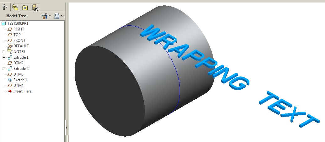
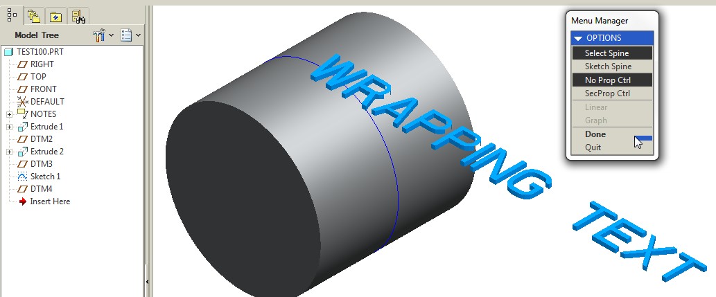
Below are the steps I am taking for the spinal bend.
1st Image: This is showing the following:
- Extruded text (tanget to the cylinder).
- Spinal sketch line (I divided the circle at the tangent edge plane for the extruded text)
2nd Image: I am choosing "Select Spine" & "No Prop Ctrl"
3rd Image:
- I selected the 'text' to be bent
- I picked the correct 'Starting Point' (shown below)
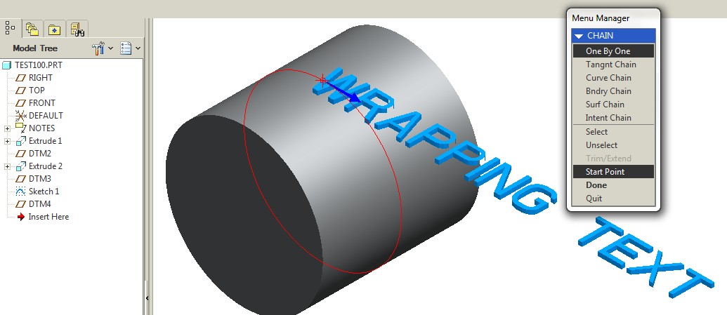
4th Image:
- I select the surface of the "T" which indicates how much of the 'Text' will be bent.
- I select 'Done'.
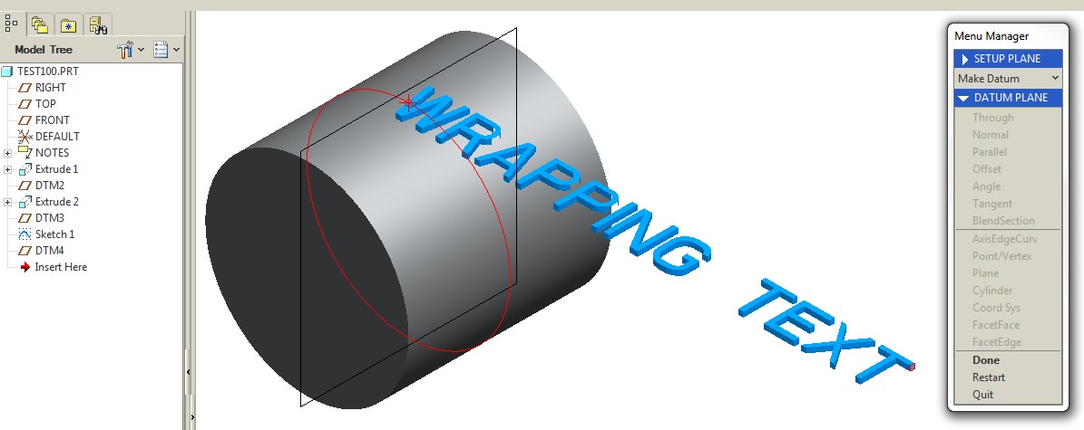
Image #5:
- BOTH my 'text' and cylinder get twisted and my parts fails....not sure why.
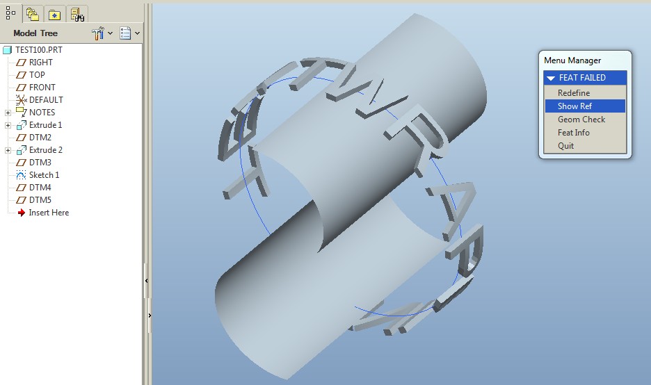
I am not sure why BOTH features are being bent.
I am close to figuring it out....I think.
- Mark as New
- Bookmark
- Subscribe
- Mute
- Subscribe to RSS Feed
- Permalink
- Notify Moderator
Since you really don't need the cylinder to make the spinal bend, you can simply offset the plane for the text.
Every solid in the model at the time of the spinal bend is acted upon, and anything outside the "region" will be cut off.
So Spinal Bend the text first and then extrude the cylinder. If you want associativity, you can use relations (parameters) or even use the sketch that you wrapped the text with.
Spinal bend does have limitations. From what understand, it has been enhanced in Creo 3.0.
- Mark as New
- Bookmark
- Subscribe
- Mute
- Subscribe to RSS Feed
- Permalink
- Notify Moderator
Do you have an end-game in mind?
Maybe we can be of more help if we know exactly what you are trying to accomplish...

- Mark as New
- Bookmark
- Subscribe
- Mute
- Subscribe to RSS Feed
- Permalink
- Notify Moderator
Oohhhh!! If EVERY feature (in the model tree) is affected when performing spinal bend then this will not help. (It's weird becuase spinal bend ask me to select the feature to be bend...oh well).
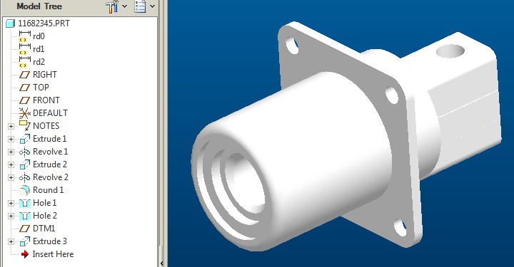
Modeling up the text and doing a spinal bend first is not really an option...our company needs to place the 'part number' on a TON of pre-modeled connector models (like the one shown below)....all these models are complete and just need the text added.
- Mark as New
- Bookmark
- Subscribe
- Mute
- Subscribe to RSS Feed
- Permalink
- Notify Moderator
I think it simply asks for a feature to know if the target is a solid or quilt. If it is a quilt, it seems to be able to do individual features.
Does WF5 have the Designated Area? If so, this was definitely the easiest way to make a surface from a text sketch. And it can be thickened easily. That way you can spinal bend a quilt rather than a solid.
Toroidal bends seem to have the same limitation.
If this isn't an option, we go back to the offset... and I understand how that could be a major issue. Those darn connectors seem to have part numbers that go on f.o.r.e.v.e.r..... ![]()
- Mark as New
- Bookmark
- Subscribe
- Mute
- Subscribe to RSS Feed
- Permalink
- Notify Moderator
I feel like I am getting closer.
Yes, I have "Designated Area" and was able to convert my sketched 'text' into a surface (nice feature!).
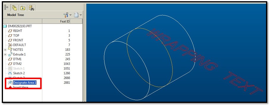
BUT; when I try to thicken the 'designated area' feature it will not let me (see below image).
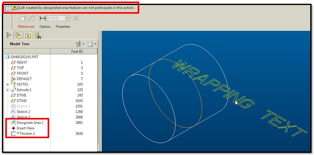
So I then tried to 'spinal bend' on just the 'designated area' feature....and it worked!! It did not distort the solidmodel. Finally....I then thickened the 'designated area'.....and it worked!!!!
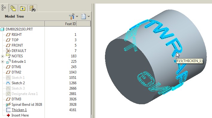
I definitly need to write myself some step-by-step instructions and post it on here for others to see down the road.
Thank you VERY MUCH Antonius....you were a HUGE help!!
- Mark as New
- Bookmark
- Subscribe
- Mute
- Subscribe to RSS Feed
- Permalink
- Notify Moderator
Disregard my comment above "I think I am getting closer"...I wrote that before I got everything to work...my apologies.
- Mark as New
- Bookmark
- Subscribe
- Mute
- Subscribe to RSS Feed
- Permalink
- Notify Moderator
We love success stories ![]()
Looking forward to a well authored Community Document on the subject ![]()
...and yes, Frank is a great inspiration to me too in ferreting out ways to accomplish things.
- Mark as New
- Bookmark
- Subscribe
- Mute
- Subscribe to RSS Feed
- Permalink
- Notify Moderator
The Following is a quick guide on how to wrap 'text' around a cylinder 360 degree's.
I received help from Antonius and Frank on this process.
I am sure there are other ways to skin this cat but this works for me (I hope this helps someone out).
Step #1: Create Datum Plane Tangent to cylinder.

Step #2: Sketch 'Text' on Datum Plane.

Step #3: Create a 'Designated Area' out of the 'text':


Step #4: Prepare for Spinal Bend by Creating the following:
- Step #4a: Create Bend Trajectory Sketch as shown below (in this example...create a circle and divide it at the tangent point assoicated to the Datum Plane in Step #1)

- Step #4b: Create datum plane located at the end of the 'text' as shown:

Step #5: Create a 'Spinal Bend' of the 'text'.

- Besure to pick the correct starting point (as shown below):

- Here is what the 'spinal bend' feature looks like (as shown below):

Step #6: Final Step....'Thicken' the 'Spinal Bend' feature.....

Again, I am sure there is more than one way to do this (and I wish PTC would just let us extrude a wrapped sketch....but at the moment we can not...are you listening PTC??)
I hope this helps someone. Goodluck!!!
Thanks again to Antonius and Frank for their help!!
-Kevin
- Mark as New
- Bookmark
- Subscribe
- Mute
- Subscribe to RSS Feed
- Permalink
- Notify Moderator
Very nice, Kevin!
I will probably do something similar in a video and post it to the Documents section so it won't get lost. It will be in Creo, however.
It is good to know that the Designated Area was available in WF5. That makes things -soooo- much easier.
On #4B... the datum plane creation for the spinal bend region; it is worth noting that careful placement of this plane will help preserve the overall width of the text. For instance, if the circumference of the surface is 3.14159... (1"OD * pi), this is the placement you want for that plane created in #4B. Even better, with foresight, you can even center the text exactly where you want. But you have to get to is backwards:
- Place the plane at the distance of the circumference of the surface where you want this centered on the surface
- Create the plane for the text sketch -opposite- the surface where you want the text centered on. The idea is that you are wrapping the "label" starting from the "backside" ...all the way around.
- Create the text sketch and center the text between the two planes (the one at the center of the feature, one at the circumference extent).
Create the Spinal path as before and create the spinal bend.
Again, this acts more like the toroidal bend where the arc length is preserved. If you decoded the toroidal bend feature, this would make this easier... again, -if- it a cylindrical feature. The hardest part of the toroidal bend is setting the wrap axis since it is cumulative with the location of the profile sketch's coordinate system.
One thing the "thicken" method will not address is draft on the text which might be useful in the case of mold design. Offset certainly works for that, but also Franks recommendations of sweep cuts will work well for this.
Just remember that not all fonts are treated equal in Creo/WF/Pro|E and some lend themselves to draft angles, and other will fail miserably.
And never overlook the simplicity of using "decal" appearance changes. Sometimes this just makes more sense than the added effort of these very involved commands.
- Mark as New
- Bookmark
- Subscribe
- Mute
- Subscribe to RSS Feed
- Permalink
- Notify Moderator
Offest has a built in draft feature, but unless I missed something (or you can do it now in creo), you cannot wrap text, only project, which drastically distorts the ends of the text.
Also, you'll need slides all over the place AND draft if this is a molded part! ![]()
- Mark as New
- Bookmark
- Subscribe
- Mute
- Subscribe to RSS Feed
- Permalink
- Notify Moderator
Offset is seriously lacking in mapping control across topology. Again, if you can wrap or otherwise map a sketch onto odd surfaces, you have to project back that distorted curve set to offset them with any semblance of "normal" wrapping. I think we would get back to the flatten quilt and flatten-quilt deformation discussion like we did with the screen mesh.
But yes, Offset does have a taper option; uncontrolled radii at the edges and surface junction; and the option of which direction you want the offset to go... fixed or according to the surface.
In general, many of the included fonts have significant draft/taper limitations. Normally, you would want the draft to increase toward the surface. By default, it decreases "line weight" so the "bold" fonts would be more useful.
- Mark as New
- Bookmark
- Subscribe
- Mute
- Subscribe to RSS Feed
- Permalink
- Notify Moderator
Awwww, now I'm getting all mushy bro! ![]()
It's nice having others including Antonius and Brian Martin to bounce ideas back and forth off of, for sure!
- Mark as New
- Bookmark
- Subscribe
- Mute
- Subscribe to RSS Feed
- Permalink
- Notify Moderator
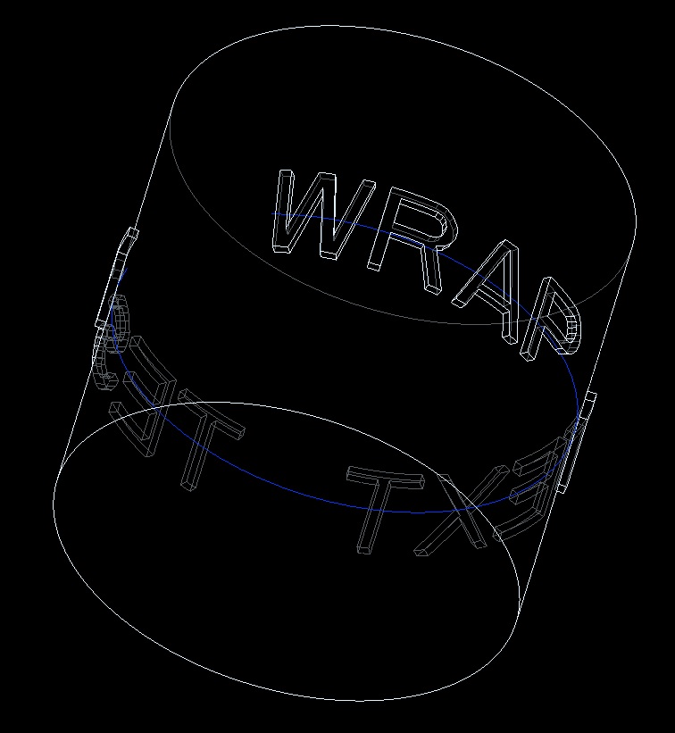
Since you can't extrude text as a surface (enhancement needed!) I had to create the text first, then toroidial bend that, then create the cylinder using the curve to drive the diameter, ensuring the text stays put. Pretty simple though.
As Antonius mentioned, you can use pi and other relations to force dims to be what you want. I used a perimiter dim (love 'em for toroidial bends!) and a reference dim to make things equal and avoid distortion.
- Mark as New
- Bookmark
- Subscribe
- Mute
- Subscribe to RSS Feed
- Permalink
- Notify Moderator
Oh and offset, while a decent tool for some things, cannot do this, at least on the version I have.
Trying to add draft failed, and to get "draft" I simply swept a cut along the edge of the text just for fun after I posted this. THAT worked.
- Mark as New
- Bookmark
- Subscribe
- Mute
- Subscribe to RSS Feed
- Permalink
- Notify Moderator
Offset works but can get finicky with angles or rounds.
- Mark as New
- Bookmark
- Subscribe
- Mute
- Subscribe to RSS Feed
- Permalink
- Notify Moderator
Also, it works like a "project", not a "wrap", at least in my version. The farther you get off center the worse it gets.
- Mark as New
- Bookmark
- Subscribe
- Mute
- Subscribe to RSS Feed
- Permalink
- Notify Moderator
Correct... it doesn't wrap at all but does project normal to the target surface. That is why you 1st wrap; then project to flat plane, and then offset back to the surface. A lot of work, really.
- Mark as New
- Bookmark
- Subscribe
- Mute
- Subscribe to RSS Feed
- Permalink
- Notify Moderator
TOO much. I'd thought about making a surface, trimming that, spinal bending that, then thickening it, but you can't pick all the elements of a curve made of text to use to trim a surface, so you're hosed. If you could do that it'd be more flexible. That and the fact you can't easily extrude text as a surface is why I did the wrapped text as the first solid feature. A kluge, for sure, but it worked.
Hmmmm, now I have another idea! ![]()
- Mark as New
- Bookmark
- Subscribe
- Mute
- Subscribe to RSS Feed
- Permalink
- Notify Moderator
I played a little more with toroidal bend. Intuition aside, it does provide a different interface from spinal bend but you are stuck using a cylindrical bend profile.
- Mark as New
- Bookmark
- Subscribe
- Mute
- Subscribe to RSS Feed
- Permalink
- Notify Moderator
OK, so, for some stupid reason you can't use text in a fill feature either, but I made a datum curve of text, made a fill surface using edges of all the letters (loops, was only a little tedious), did a spinal bend on that, then thickened that surface. Wasn't too painful 95 features vs. 3), but it allows for several spinal bends anywhere in the model tree if needed. If any of the surface commands allowed text this would be SO much simpler (back to 3 features). Makes no sense that they don't. ![]()
- Mark as New
- Bookmark
- Subscribe
- Mute
- Subscribe to RSS Feed
- Permalink
- Notify Moderator
In the cosmetic features area, Creo 2.0 now has a "designated area" feaure.
This will fill text directly from a sketch.
Here a toroidal bend is acting on the resulting surface quilt of the Designated Area feature.
I found this by accident. And you are right, many commands do not recognize sketch text as a valid geometric feature.
- Mark as New
- Bookmark
- Subscribe
- Mute
- Subscribe to RSS Feed
- Permalink
- Notify Moderator
Hmmm, gonna have to try that tomorrow, thanks! ![]()


