
Turn on suggestions
Auto-suggest helps you quickly narrow down your search results by suggesting possible matches as you type.
Showing results for
Please log in to access translation
Turn on suggestions
Auto-suggest helps you quickly narrow down your search results by suggesting possible matches as you type.
Showing results for
Community Tip - Visit the PTCooler (the community lounge) to get to know your fellow community members and check out some of Dale's Friday Humor posts! X
- Community
- Creo+ and Creo Parametric
- 3D Part & Assembly Design
- Re: How to assemble to Sheet Metal Holes
Translate the entire conversation x
Please log in to access translation
Options
- Subscribe to RSS Feed
- Mark Topic as New
- Mark Topic as Read
- Float this Topic for Current User
- Bookmark
- Subscribe
- Mute
- Printer Friendly Page
How to assemble to Sheet Metal Holes
Sep 12, 2014
05:43 AM
- Mark as New
- Bookmark
- Subscribe
- Mute
- Subscribe to RSS Feed
- Permalink
- Notify Moderator
Please log in to access translation
Sep 12, 2014
05:43 AM
How to assemble to Sheet Metal Holes
Hello,
I have a user who has modelled some parts in sheet metal.
They consist of curved vanes, some 6" x1/2" in cross section and 6 feet long. They are bent around a constant radius over the last 2 feet or so.
Whilst in the flat state, some holes are drilled through the vanes. Once bent, the holes appear in the bent model at the correct angle.
The problem arises when we try to assemble things. Pro/E understands the holes in the unbent position. They only seem to exist in the bent position as surfaces. The bent holes have no axes and we therefore cannot assemble screws, etc. to them.
Any suggestions?
My suggestion was that he models them all again as solids, rather than as sheet metal, but that wasn't popular...
WF4, m220
John Wayman
This thread is inactive and closed by the PTC Community Management Team. If you would like to provide a reply and re-open this thread, please notify the moderator and reference the thread. You may also use "Start a topic" button to ask a new question. Please be sure to include what version of the PTC product you are using so another community member knowledgeable about your version may be able to assist.
Labels:
- Labels:
-
Sheet Metal Design
9 REPLIES 9
Sep 12, 2014
10:15 AM
- Mark as New
- Bookmark
- Subscribe
- Mute
- Subscribe to RSS Feed
- Permalink
- Notify Moderator
Please log in to access translation
Sep 12, 2014
10:15 AM
John,
What WF sheet metal techniqe was used to create the vanes? I have done some projects where I needed to assemble things to "bent and twisted" features.
Can you share a picture or a sample model?
Dean
Sep 12, 2014
10:59 AM
- Mark as New
- Bookmark
- Subscribe
- Mute
- Subscribe to RSS Feed
- Permalink
- Notify Moderator
Please log in to access translation
Sep 12, 2014
10:59 AM
You can add points or coordinate systems to the holes in the flat state and they should follow the bent feature.
Not sure where the axes went. Do they not appear in the flat state?
The problem you are seeing is because the holes are no longer round after being formed. This is because in sheetmetal only one surface drives all the sheetmetal geometry features - when that surface is warped or formed, all the features driven from it are warped as well. If a hole is in a place that stays flat after bending, it would still be a hole.
Sep 13, 2014
12:35 AM
- Mark as New
- Bookmark
- Subscribe
- Mute
- Subscribe to RSS Feed
- Permalink
- Notify Moderator
Please log in to access translation
Sep 13, 2014
12:35 AM
I can get the axes to follow the bend back feature but the reference pattern fails to follow past the bend. It is a tedious assembly. Avoid trying to use tangent as it seems to always create the tangent opposite where you want it with no "next solution" available. As David recommends, you can place points at the intersect of a rounded plane (cylindrical) and the axis. Then you have an axis for alignment and a point for "depth". You will need that point in both features, though. CSYS might be better, but they too require a lot of "maintenance". Why can we not have a CSYS mate to a point as a constraint?
Sep 17, 2014
10:14 AM
- Mark as New
- Bookmark
- Subscribe
- Mute
- Subscribe to RSS Feed
- Permalink
- Notify Moderator
Please log in to access translation
Sep 17, 2014
10:14 AM
Thanks for the answers, folks.
I have just returned after a lovely long weekend in Rome, so I apologise for not having replied earlier, but I did have other things on my mind...

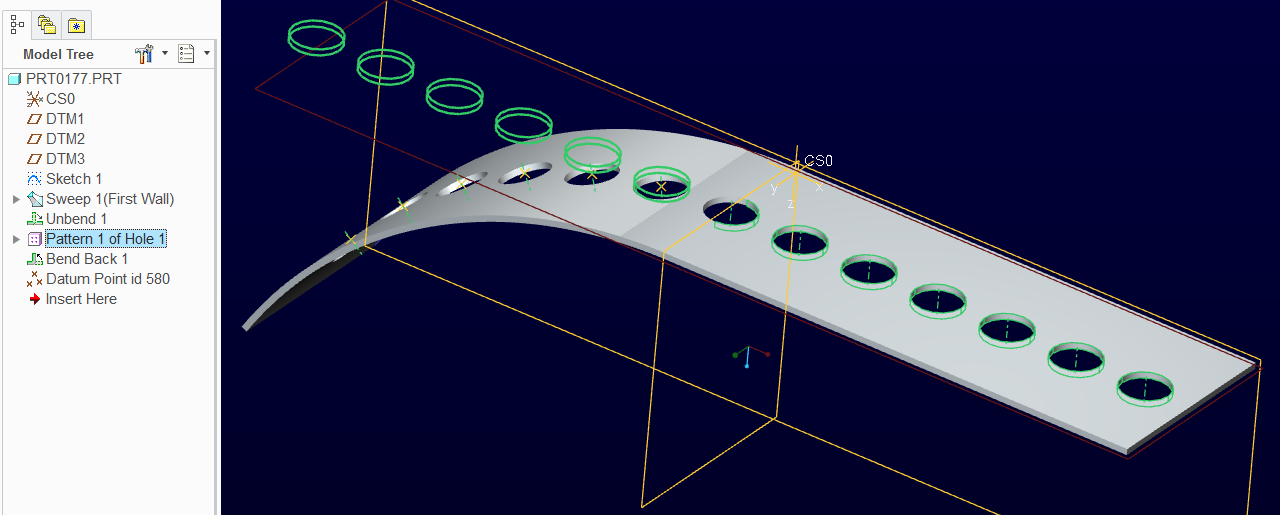
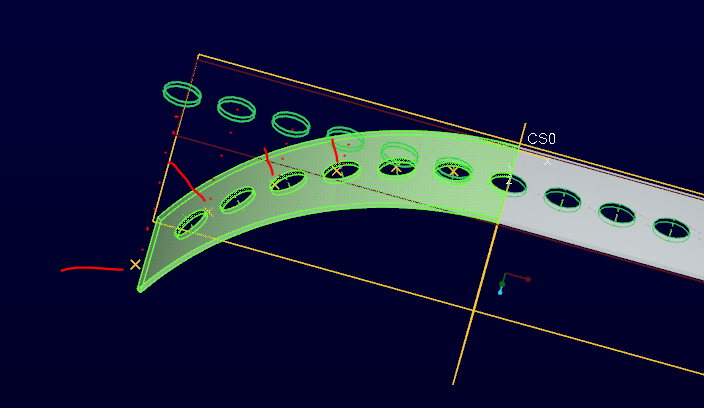
The picture shows the model tree and the bent item, with the hole axes marooned in free space.
I tried placing another set of axes, through a point and normal to the surface, before the bend feature, and got the same result, just with some additional marooned points.
I also tried doing the bend first, then an unbend before adding the holes and finally a bend-back. Still the same result.
Where are we going wrong?
We don't use sheet metal much - you probably guessed that. I'm sure I've cracked this one previously, though.
Any suggestions (other than to ditch WF4 and use Creo Parametric 3.0...)?
WF4, m220
Cheers,
John
Sep 17, 2014
01:17 PM
- Mark as New
- Bookmark
- Subscribe
- Mute
- Subscribe to RSS Feed
- Permalink
- Notify Moderator
Please log in to access translation
Sep 17, 2014
01:17 PM
John, I've had axes do both things... stay on the flat position in some instances and others it would go with the metal. The axes should be created with the feature and maybe they are hiding with intelligent layers.
This is Creo 2.0. You can probably follow the structure. You also see that the axes moved with the bend-back.
However, opening this part today, the points I placed at the intersections of axis and surface moved off to a projected state from the flat until I edited the definision of the points. Bad form!
I guess I better report this one.
Sep 17, 2014
02:15 PM
- Mark as New
- Bookmark
- Subscribe
- Mute
- Subscribe to RSS Feed
- Permalink
- Notify Moderator
Please log in to access translation
Sep 17, 2014
02:15 PM
Can we all agree that it performs to spec?
Sep 17, 2014
02:29 PM
- Mark as New
- Bookmark
- Subscribe
- Mute
- Subscribe to RSS Feed
- Permalink
- Notify Moderator
Please log in to access translation
Sep 17, 2014
02:29 PM
We'll see... Support has already filed my error as SPR 2242012. I filed it as a high severity case.
Just about anything I change in my file will cause the points to revert to projecting from the flat state. Regen doesn't catch it but edit definition and moving the "insert here" bar will.
I'm sure there is some logic accounted for in the specifications, but who knows what that logic is.
Sep 17, 2014
03:06 PM
- Mark as New
- Bookmark
- Subscribe
- Mute
- Subscribe to RSS Feed
- Permalink
- Notify Moderator
Please log in to access translation
Sep 17, 2014
03:06 PM
It appears that on that part a function is returning a pointer to the un-transformed axes instead of the transformed axes. There are probably two different functions that can be called to get the feature members, one of which is returning the pre-formed feature and the other the post-formed one. Hence, now you see it, now you don't, depending on the path to the evaluation function.
In WF 5 I had a part with patterned cuts that got Ref Pattern of projected curves in the flat state.
There were 4 cuts.
There were 5 projected curves.
The flat pattern of the part would leave one of the curves floating off the end of the part.
No maintenance, so no bug report.
For a while I thought that projected curves onto sheetmetal were resolved by performing a clipping operation on each triangle making up the surface, doing the forming transformation, and then just connecting the dots. This seemed reasonable and an explanation for why you can't project a crosshair** over a hole - there is no surface in the hole to tesslate, no triangle from tesselation, and therefore no triangle to clip against.
Then I got the part with the projected curves off in space with no surface under them at all. Sigh.
**It was using sheetmetal for fabric assemblies. The cross hair is drawn in using pen on the fabric cutting table so the sewing crew has something to line up on. It really is just the four tic marks that remain, but it is much easier to draw two lines ref'ed to the circle center and let the cutting table remove the middle circle than to do four line stubs that ref the perimeter.
Sep 17, 2014
03:17 PM
- Mark as New
- Bookmark
- Subscribe
- Mute
- Subscribe to RSS Feed
- Permalink
- Notify Moderator
Please log in to access translation
Sep 17, 2014
03:17 PM
It really bugs me when a part suddenly changes attributes for no reason at all.
This one I can see create a real issue between me, my client, and my suppliers.
Not acceptable!
I'm just glad it is reproducible and that engineering will have a look at it.


