
Turn on suggestions
Auto-suggest helps you quickly narrow down your search results by suggesting possible matches as you type.
Showing results for
Please log in to access translation
Turn on suggestions
Auto-suggest helps you quickly narrow down your search results by suggesting possible matches as you type.
Showing results for
Community Tip - Stay updated on what is happening on the PTC Community by subscribing to PTC Community Announcements. X
- Community
- Creo+ and Creo Parametric
- 3D Part & Assembly Design
- Re: How to create a nozzle removing material with ...
Translate the entire conversation x
Please log in to access translation
Options
- Subscribe to RSS Feed
- Mark Topic as New
- Mark Topic as Read
- Float this Topic for Current User
- Bookmark
- Subscribe
- Mute
- Printer Friendly Page
How to create a nozzle removing material with variable section sweep?
Feb 25, 2013
11:28 AM
- Mark as New
- Bookmark
- Subscribe
- Mute
- Subscribe to RSS Feed
- Permalink
- Notify Moderator
Please log in to access translation
Feb 25, 2013
11:28 AM
How to create a nozzle removing material with variable section sweep?
Hi!
I need some help on below:
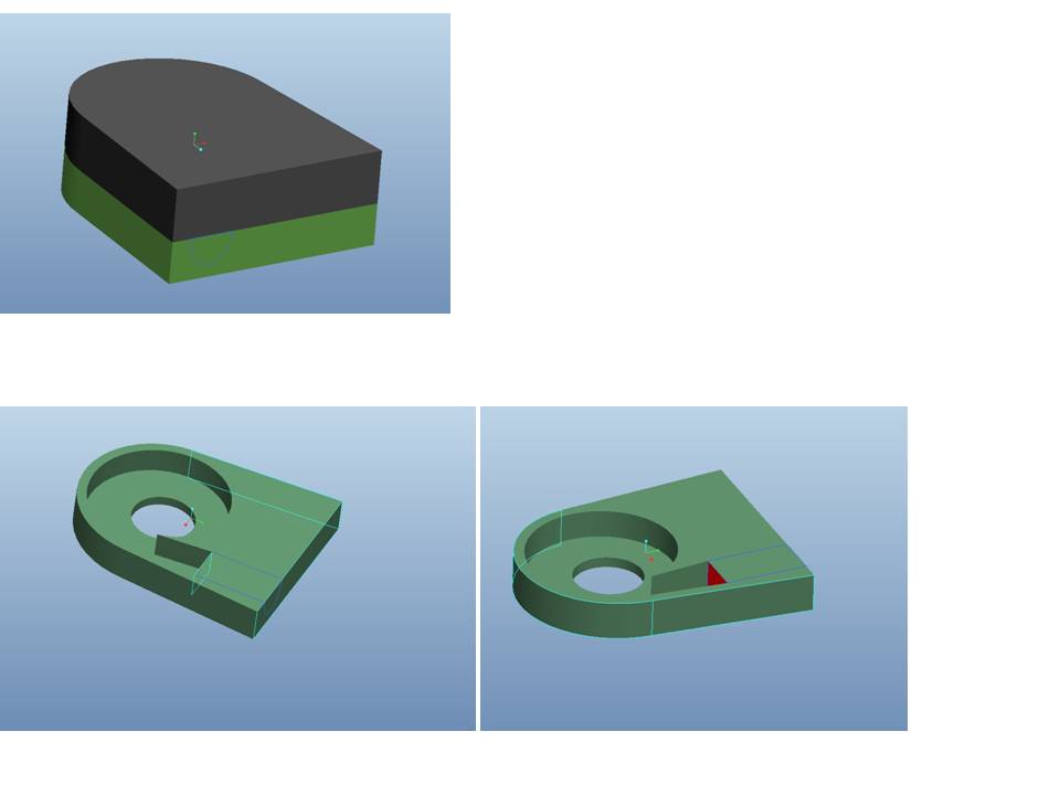
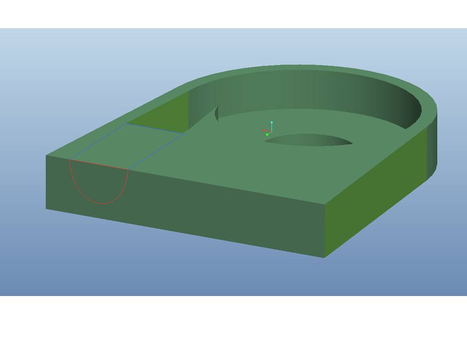
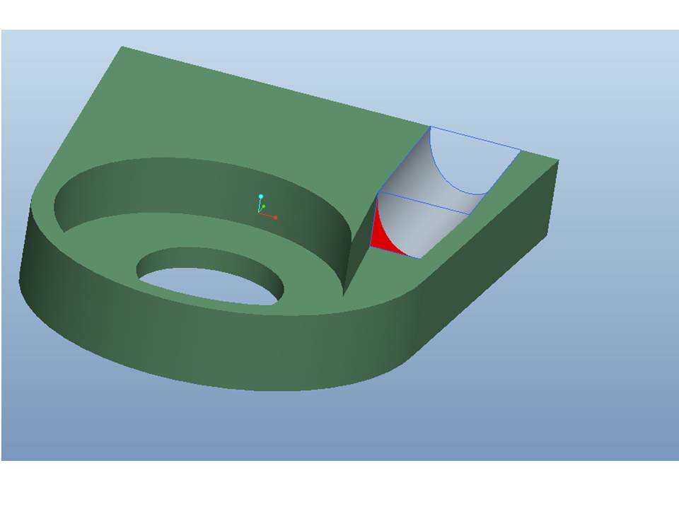
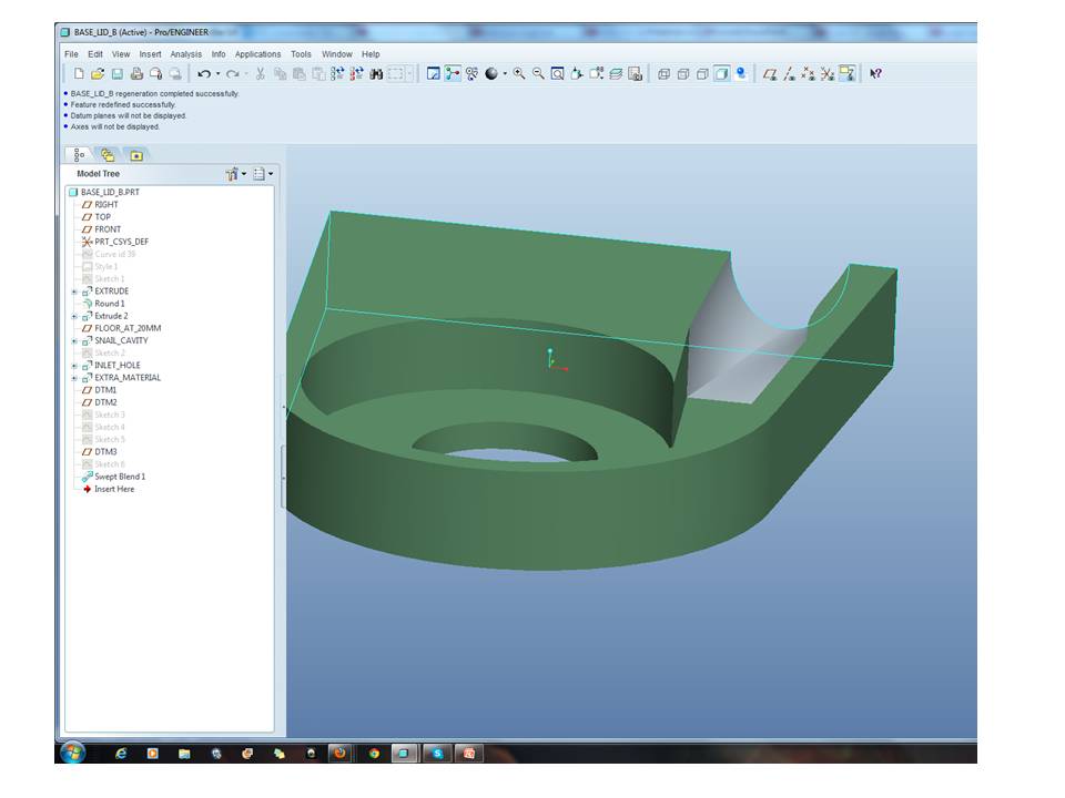
I am working on a plastic casing that has two main components as shown in the very first picture. There is already an inner cavity (turbine shaped cut to accept water) that ends to a rectangular opening. Client asked me to add material and extend this nozzle so that in the next 15cm to turn into a circle or ellipsis of same area.
In other words, we need to cut a almost tubular nozzle, which starts as rectangular and ends smoothly as circle or ellipsis.
Pls see in red above, the rectangular surface where removing material should start.
Since the ELLIPTICAL OUTLET OF NOZZLE should be created by the assembly of the two parts, we need half of the cut at each part.
That is why I have sketched a curve on the surface that we be removed to have it a refererce.
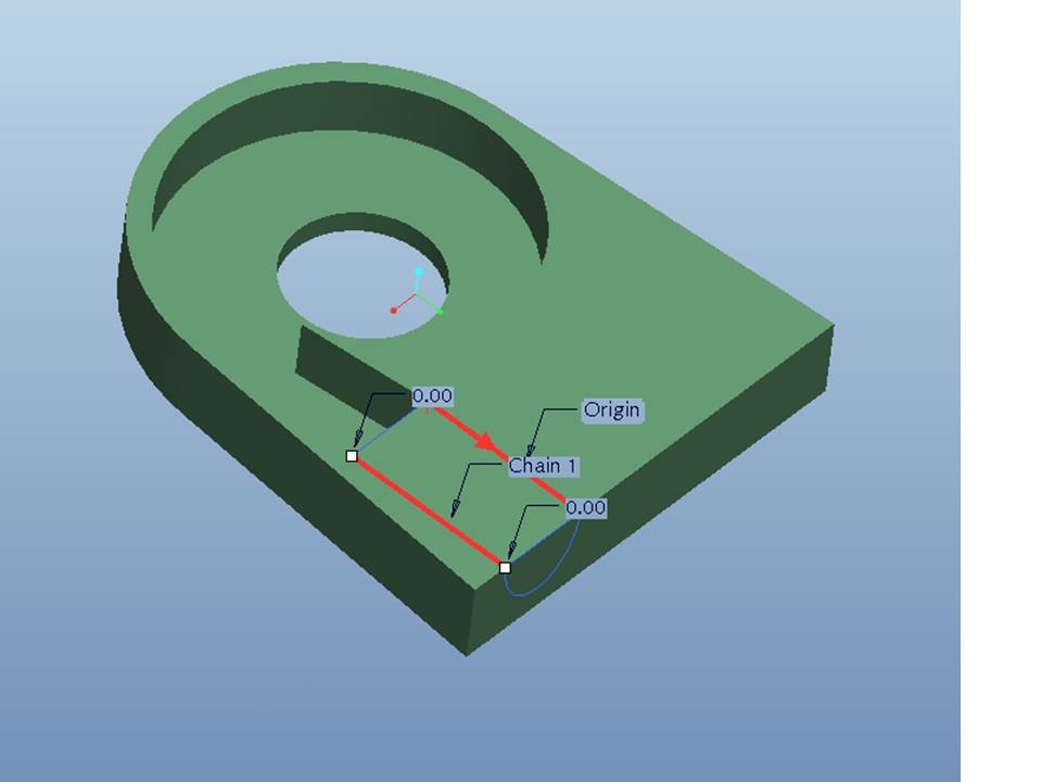
I tried Variable Section Sweep , with two trajectories that lead from the rencangular to the hald-ellipsis shape and I sketched a half ellipsis section.
And I get this:
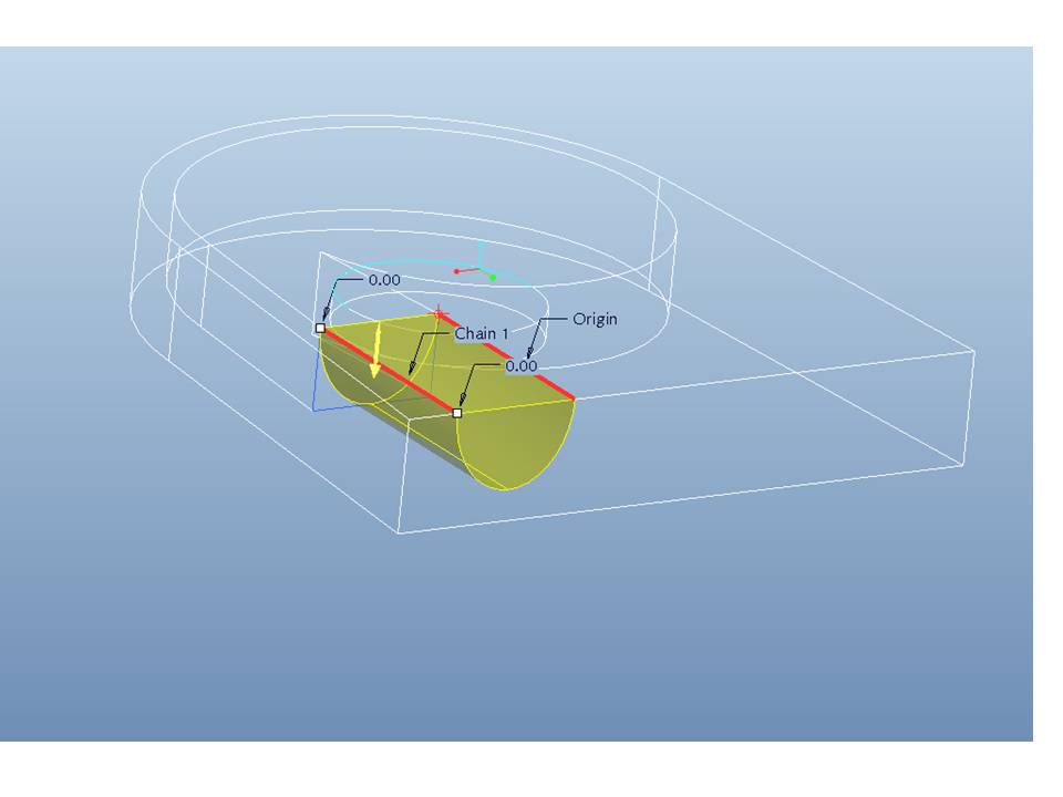
which of course is not variable section cut, but only one section.
This cannot give me a smooth trancation for rectangular to elliptical opening.
Any advise or amendment to my thought?
I am not very familiar with variable section sweeps but I think there might be an easy way that I just dont know.
Please help me , the soonest the better. I m in despair! 
Thanks,
Amanda
This thread is inactive and closed by the PTC Community Management Team. If you would like to provide a reply and re-open this thread, please notify the moderator and reference the thread. You may also use "Start a topic" button to ask a new question. Please be sure to include what version of the PTC product you are using so another community member knowledgeable about your version may be able to assist.
Solved! Go to Solution.
Labels:
- Labels:
-
Assembly Design
ACCEPTED SOLUTION
Accepted Solutions
Feb 25, 2013
02:01 PM
- Mark as New
- Bookmark
- Subscribe
- Mute
- Subscribe to RSS Feed
- Permalink
- Notify Moderator
Please log in to access translation
Feb 25, 2013
02:01 PM
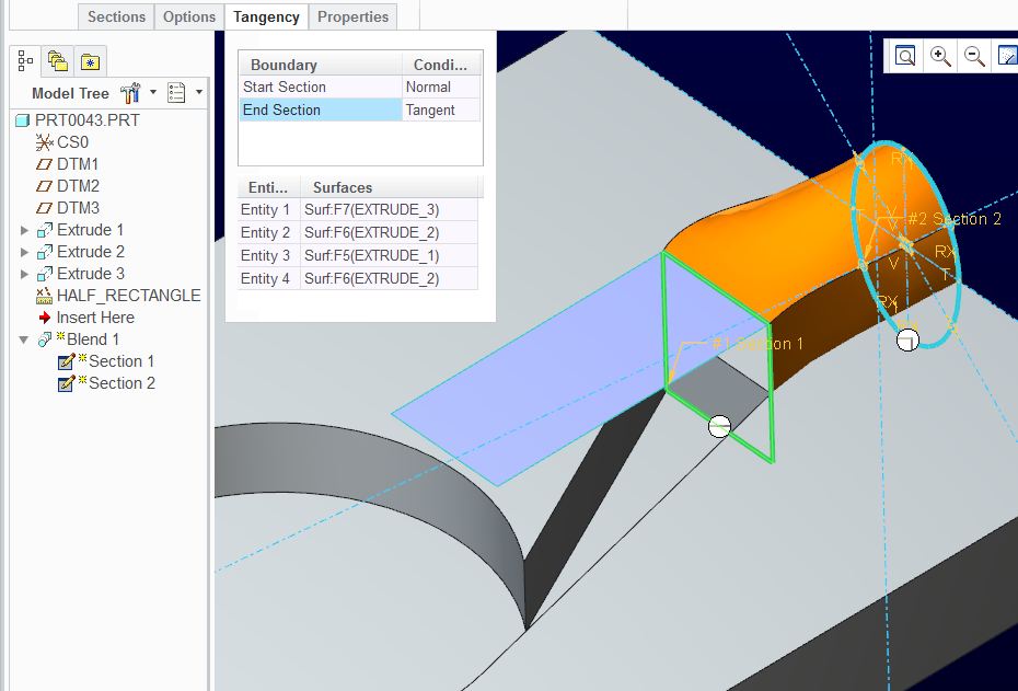
And just for completeness, I took this to the next level and added tangency to the tapered surfaces. Since I was using the "full" section, I needed a surface to define one of the tangencies (blue surface on top). Now the rectangular end is tangent to all 4 faces entering the rectangle and all the transitions are smooth.
35 REPLIES 35
Feb 25, 2013
11:58 AM
- Mark as New
- Bookmark
- Subscribe
- Mute
- Subscribe to RSS Feed
- Permalink
- Notify Moderator
Please log in to access translation
Feb 25, 2013
11:58 AM
You just need the same number of segments in each sketch so you may need to break up the ellipse in the right locations. There is also no need to make only half the feature since it is a remove material feature.
I'll give it a try but that is the jest of it.
Feb 25, 2013
12:21 PM
- Mark as New
- Bookmark
- Subscribe
- Mute
- Subscribe to RSS Feed
- Permalink
- Notify Moderator
Please log in to access translation
Feb 25, 2013
12:21 PM
Yep, that works. Simplified version:
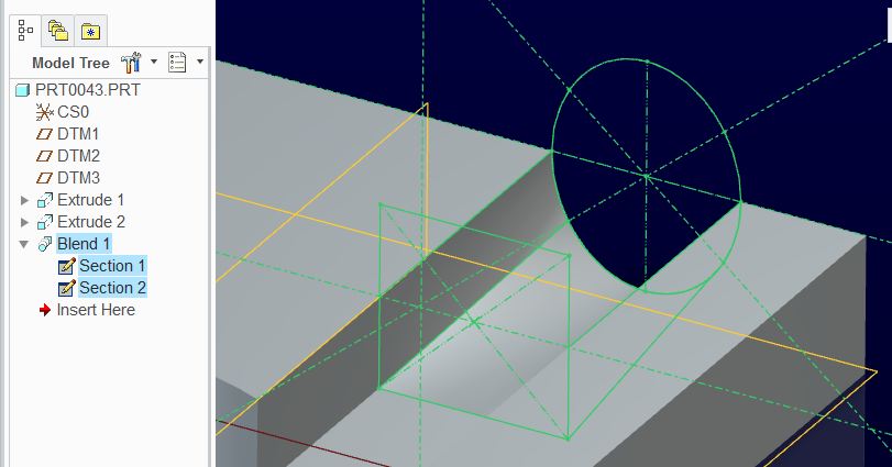
The crossed centerlines are used to define the ellipse "break point" by using "Divide" in the editing group/
You can control the ellipse in one of many way. Just know that a divided ellipse becomes a handful to manage as they now require constrains for each segment.
You get the options to make the ends straight, smooth, or tangent, etc.
This should all work the same way with blend in your version.
Feb 25, 2013
12:28 PM
- Mark as New
- Bookmark
- Subscribe
- Mute
- Subscribe to RSS Feed
- Permalink
- Notify Moderator
Please log in to access translation
Feb 25, 2013
12:28 PM
I am trying to understand what do you mean by dividing ellipse!
I have to draw also in sketch the crossed centerlines in order to get them as entities?
and what is the " divide " in "EDITING tree" ?! I need to go to the model tree and select any "divide" option?
I need a hint please!
Feb 25, 2013
12:01 PM
- Mark as New
- Bookmark
- Subscribe
- Mute
- Subscribe to RSS Feed
- Permalink
- Notify Moderator
Please log in to access translation
Feb 25, 2013
12:01 PM
The easiest approach might be to use a variable round, starting very small to give a rectangle with slightly rounded corners and finishing very large to give a circle, or very close.
Otherwise I think you're looking for a Swept Blend; the trick to remember is that each section within it must have the same number of entities - so if you draw three sides of a rectangle in the first section, you need to break up your semi-circle into three sections in the last one.
Feb 25, 2013
12:04 PM
- Mark as New
- Bookmark
- Subscribe
- Mute
- Subscribe to RSS Feed
- Permalink
- Notify Moderator
Please log in to access translation
Feb 25, 2013
12:04 PM
....unless you do a blend vertex.... 
Feb 25, 2013
12:32 PM
- Mark as New
- Bookmark
- Subscribe
- Mute
- Subscribe to RSS Feed
- Permalink
- Notify Moderator
Please log in to access translation
Feb 25, 2013
12:32 PM
Is it an extra feature in swept blend? Doesnt count the number of entinties?
Feb 25, 2013
12:24 PM
- Mark as New
- Bookmark
- Subscribe
- Mute
- Subscribe to RSS Feed
- Permalink
- Notify Moderator
Please log in to access translation
Feb 25, 2013
12:24 PM
I am trying now swept blend and I can see the problem with number of entinties! How can I have same entities, renctangular has 4 so as to be closed and ellipsis has 1 if whole or 2 if half.
How to I make it ?
Feb 25, 2013
12:38 PM
- Mark as New
- Bookmark
- Subscribe
- Mute
- Subscribe to RSS Feed
- Permalink
- Notify Moderator
Please log in to access translation
Feb 25, 2013
12:38 PM
This is where I get lost because I do not have WF5...
how do you break up a circle in your sketcher?
In other words, you need to create 4 segments of an ellipse and constrain each.
In Creo, you get a "divide" operation inside sketcher. The centerlines control the location of that division. Creo also has a "delete segment" which can be used to break up circles or sections of curves rather than trimming them manually.
Those break points on the ellipse are fairly important in practice as as they will define what would be a critical transition feature. As you stated, the -area- must be the same... where the ratio of the edge length too should correspond for each quadrant. in other words, if the rectangle is a perfect square and you have the area-matching figured out, the break points should be evenly divided around the ellipse.
Feb 25, 2013
12:45 PM
- Mark as New
- Bookmark
- Subscribe
- Mute
- Subscribe to RSS Feed
- Permalink
- Notify Moderator
Please log in to access translation
Feb 25, 2013
12:45 PM
The rectangle is not square so there are not equal pieces
I have dimensions 80.2mmx50.9mm for the rectangle.
So I understand that I must complete the simple Blend (as a CUT) command in 4 steps, each one for one piece of ellipse, since there is no divide option.
right!?
Still havent got it ,but I m trying!
Feb 25, 2013
12:57 PM
- Mark as New
- Bookmark
- Subscribe
- Mute
- Subscribe to RSS Feed
- Permalink
- Notify Moderator
Please log in to access translation
Feb 25, 2013
12:57 PM
I mis-remembered - Swept Blend needs a trajectory, so I don't think that's what's needed here.
Boundary Blend using two external sketches seems to work, but may only create a surface which you'll then have to Solidify:
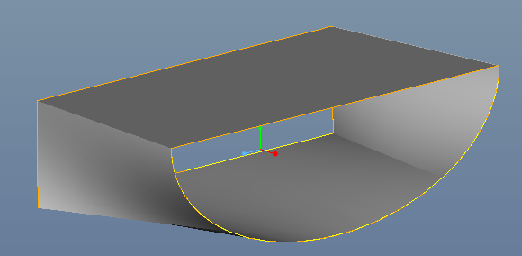
The sections don't need to be equal; there just has to be the same number (4 in this case). The position of the divide points will change the geometry of the blend, though (making the bottom surface closer to a triangle, or closer to a rectangle).
Feb 25, 2013
02:19 PM
- Mark as New
- Bookmark
- Subscribe
- Mute
- Subscribe to RSS Feed
- Permalink
- Notify Moderator
Please log in to access translation
Feb 25, 2013
02:19 PM
Even if I solify a blend like this, how can I work it on reverse, meaning , remove - cut material for solid part???
Feb 26, 2013
03:34 AM
- Mark as New
- Bookmark
- Subscribe
- Mute
- Subscribe to RSS Feed
- Permalink
- Notify Moderator
Please log in to access translation
Feb 26, 2013
03:34 AM
The "solidify" feature can either add material, or cut it away - just click the 'cut' button in the solidify dashboard.
For the blend that I created, you may first need to add end surfaces and merge them into the original blend to create a closed quilt, in order to make a solidify work reliably.
Feb 26, 2013
09:42 AM
- Mark as New
- Bookmark
- Subscribe
- Mute
- Subscribe to RSS Feed
- Permalink
- Notify Moderator
Please log in to access translation
Feb 26, 2013
09:42 AM
It can also do both at the same time. Much like the old "Tweak, Surface Replace" command.
Feb 26, 2013
10:47 AM
- Mark as New
- Bookmark
- Subscribe
- Mute
- Subscribe to RSS Feed
- Permalink
- Notify Moderator
Please log in to access translation
Feb 26, 2013
10:47 AM
I am not familiar with this one! 
Feb 26, 2013
10:47 AM
- Mark as New
- Bookmark
- Subscribe
- Mute
- Subscribe to RSS Feed
- Permalink
- Notify Moderator
Please log in to access translation
Feb 26, 2013
10:47 AM
Tonight is the night...I will try this as well and let you know! Thanks!
Feb 25, 2013
01:08 PM
- Mark as New
- Bookmark
- Subscribe
- Mute
- Subscribe to RSS Feed
- Permalink
- Notify Moderator
Please log in to access translation
Feb 25, 2013
01:08 PM
Yes it is simple blend, and you only need to do this once. You do have a divide feature in your sketcher. It is that lonely little button at the bottom that rarely gets used 
For your purposes, it may not matter exactly where you divide the ellipse. It is a lot more work managing the quadrants of the ellipse to be an accurate ratio to the rectangle. If turbulence was a significant issue to contend with, this "problem" would get much bigger quickly.
Feb 25, 2013
12:31 PM
- Mark as New
- Bookmark
- Subscribe
- Mute
- Subscribe to RSS Feed
- Permalink
- Notify Moderator
Please log in to access translation
Feb 25, 2013
12:31 PM
i foun also this on youtube, but since the entities must be same number how he makes it work with a rectangular and a circle!? (ps. I can not understand what he says, I just watch)
Feb 25, 2013
12:41 PM
- Mark as New
- Bookmark
- Subscribe
- Mute
- Subscribe to RSS Feed
- Permalink
- Notify Moderator
Please log in to access translation
Feb 25, 2013
12:41 PM
The video shows that the circle is broken up and the breaks are controlled by relations and dimensions (@0:28).
Feb 25, 2013
12:47 PM
- Mark as New
- Bookmark
- Subscribe
- Mute
- Subscribe to RSS Feed
- Permalink
- Notify Moderator
Please log in to access translation
Feb 25, 2013
12:47 PM
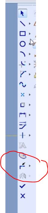
You have "divide" in your WF5 sketcher... 4th button up from the bottom.
Feb 25, 2013
01:19 PM
- Mark as New
- Bookmark
- Subscribe
- Mute
- Subscribe to RSS Feed
- Permalink
- Notify Moderator
Please log in to access translation
Feb 25, 2013
01:19 PM
I was blind so long time bfr! Ok , this really useful!
Feb 25, 2013
01:17 PM
- Mark as New
- Bookmark
- Subscribe
- Mute
- Subscribe to RSS Feed
- Permalink
- Notify Moderator
Please log in to access translation
Feb 25, 2013
01:17 PM
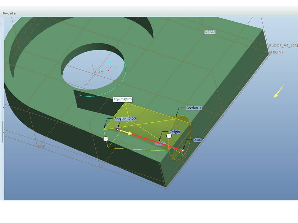
Ok, I broke the ellipse into 4 segments, so it was accepted to get together with the rectangle.
However, it is not a smooth transaction. Somehow ti TURNS/TWISTS in the inside and gives me no option to make it straight.
Have I missed sth?
Feb 25, 2013
01:20 PM
- Mark as New
- Bookmark
- Subscribe
- Mute
- Subscribe to RSS Feed
- Permalink
- Notify Moderator
Please log in to access translation
Feb 25, 2013
01:20 PM
... yep, you have to control where those breaks are.
I added the "smooth" and "normal" tangency to the feature's ends and ended up with this (shown uncut for clarity)
Look where the transition lines go to:
Now you see why the centerline were included.
Feb 25, 2013
02:01 PM
- Mark as New
- Bookmark
- Subscribe
- Mute
- Subscribe to RSS Feed
- Permalink
- Notify Moderator
Please log in to access translation
Feb 25, 2013
02:01 PM
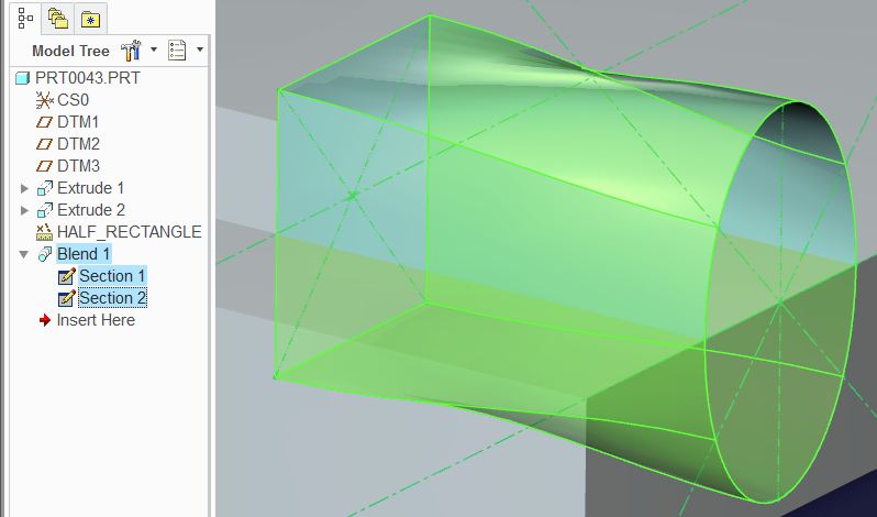
And just for completeness, I took this to the next level and added tangency to the tapered surfaces. Since I was using the "full" section, I needed a surface to define one of the tangencies (blue surface on top). Now the rectangular end is tangent to all 4 faces entering the rectangle and all the transitions are smooth.
Feb 25, 2013
02:16 PM
- Mark as New
- Bookmark
- Subscribe
- Mute
- Subscribe to RSS Feed
- Permalink
- Notify Moderator
Please log in to access translation
Feb 25, 2013
02:16 PM
OK I am almost there I think to get. I will apply your tips and upload my result.
I need to check carefully again all the options! As I said, I m not really familiar with blend commands.
I will revert .
However, as far as I can see, the cut will never be smooth 100%.
And the problem is that this a cut in order to create the inner surface of a water nozzle.
I need straight lines to the wall or else there will be turbulance of water and speed loss.
I am also thinking about interfere more than 2 sections, starting with a rectangle, then rectangle with rounded edges , then more rounded, then almost elliptical shape and finally circle.
Too much maybe but it might gives me a smoother than all transition or NOT?
Feb 25, 2013
02:29 PM
- Mark as New
- Bookmark
- Subscribe
- Mute
- Subscribe to RSS Feed
- Permalink
- Notify Moderator
Please log in to access translation
Feb 25, 2013
02:29 PM
True that this would want some optimization. Maintaining a constant cross-sectional area is critical to avoid cavitation.
I have attached a STEP file of what my end result came up with using the tangent/normal end.
Feb 25, 2013
03:56 PM
- Mark as New
- Bookmark
- Subscribe
- Mute
- Subscribe to RSS Feed
- Permalink
- Notify Moderator
Please log in to access translation
Feb 25, 2013
03:56 PM
I opened and checked your stp. Seems to be smooth enough since it lets only slight edge in the inner cavity after the removal. I will play a liitle with 4 segments of circle and tangent option and I will post my results.... tmr night i believe! waiting feedback from client , if it will be an ellipse or a circle , finally!
thanks for responding so far!
Feb 25, 2013
04:57 PM
- Mark as New
- Bookmark
- Subscribe
- Mute
- Subscribe to RSS Feed
- Permalink
- Notify Moderator
Please log in to access translation
Feb 25, 2013
04:57 PM
I haven't pushed the blend feature this far before. Thanks again for the challenge. I am certain this knowledge will be useful soon enough. Good luck with the client!
Feb 26, 2013
10:58 AM
- Mark as New
- Bookmark
- Subscribe
- Mute
- Subscribe to RSS Feed
- Permalink
- Notify Moderator
Please log in to access translation
Feb 26, 2013
10:58 AM
The bad thing with Research & Development models is that given data change and change again and the designer needs to amend and redesign like a programmed robot. This of course only happens, when research is not adequate at first place.
But you propably know, that this is a client's call, not mine. I just make their "vision" in 3d and then ready for manufacture!
Wish me luck!
(I m trying to do my best as a self-tutored Pro E child!)
Feb 26, 2013
01:22 PM
- Mark as New
- Bookmark
- Subscribe
- Mute
- Subscribe to RSS Feed
- Permalink
- Notify Moderator
Please log in to access translation
Feb 26, 2013
01:22 PM
You just described the last 12 years of my life 


