
Turn on suggestions
Auto-suggest helps you quickly narrow down your search results by suggesting possible matches as you type.
Showing results for
Please log in to access translation
Turn on suggestions
Auto-suggest helps you quickly narrow down your search results by suggesting possible matches as you type.
Showing results for
Community Tip - You can change your system assigned username to something more personal in your community settings. X
- Community
- Creo+ and Creo Parametric
- 3D Part & Assembly Design
- Re: How to create a nozzle removing material with ...
Translate the entire conversation x
Please log in to access translation
Options
- Subscribe to RSS Feed
- Mark Topic as New
- Mark Topic as Read
- Float this Topic for Current User
- Bookmark
- Subscribe
- Mute
- Printer Friendly Page
How to create a nozzle removing material with variable section sweep?
Feb 25, 2013
11:28 AM
- Mark as New
- Bookmark
- Subscribe
- Mute
- Subscribe to RSS Feed
- Permalink
- Notify Moderator
Please log in to access translation
Feb 25, 2013
11:28 AM
How to create a nozzle removing material with variable section sweep?
Hi!
I need some help on below:
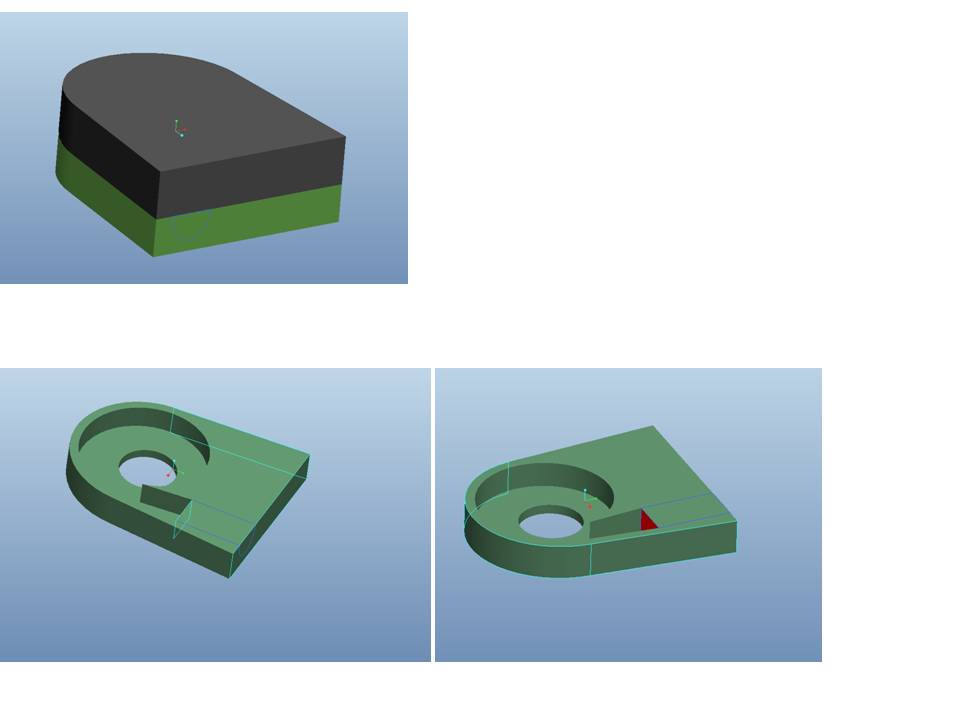
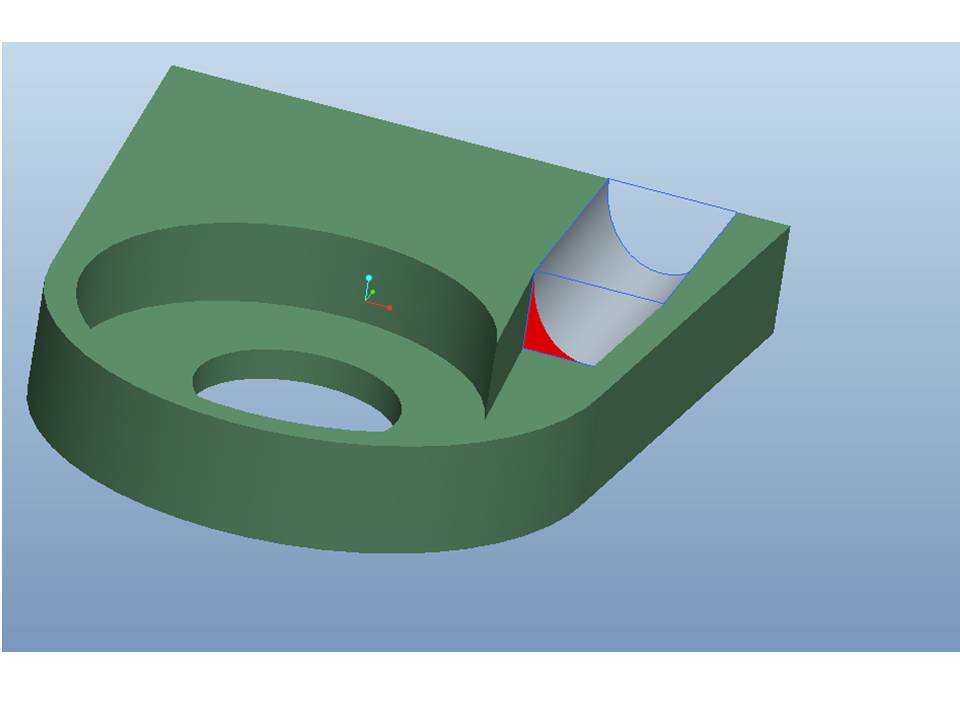
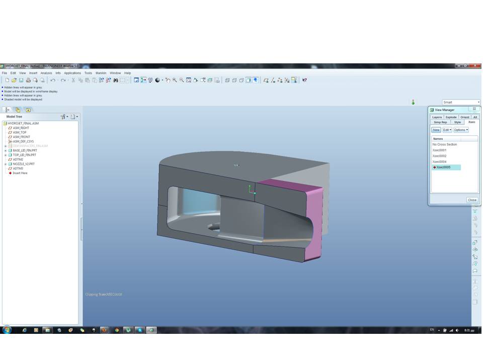
I am working on a plastic casing that has two main components as shown in the very first picture. There is already an inner cavity (turbine shaped cut to accept water) that ends to a rectangular opening. Client asked me to add material and extend this nozzle so that in the next 15cm to turn into a circle or ellipsis of same area.
In other words, we need to cut a almost tubular nozzle, which starts as rectangular and ends smoothly as circle or ellipsis.
Pls see in red above, the rectangular surface where removing material should start.
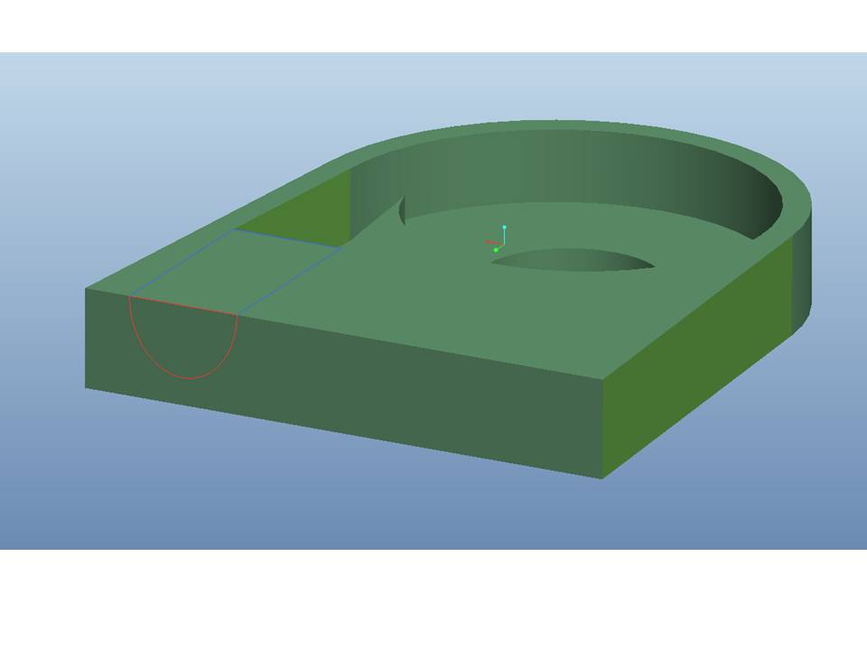
Since the ELLIPTICAL OUTLET OF NOZZLE should be created by the assembly of the two parts, we need half of the cut at each part.
That is why I have sketched a curve on the surface that we be removed to have it a refererce.
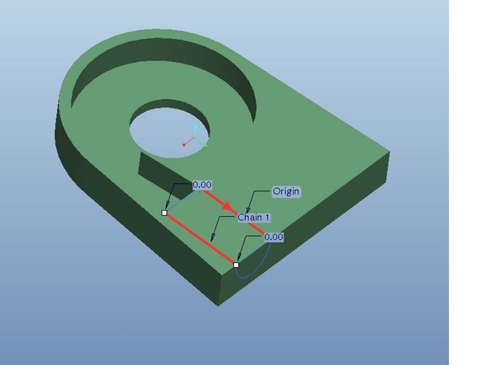
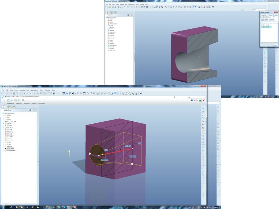
I tried Variable Section Sweep , with two trajectories that lead from the rencangular to the hald-ellipsis shape and I sketched a half ellipsis section.
And I get this:
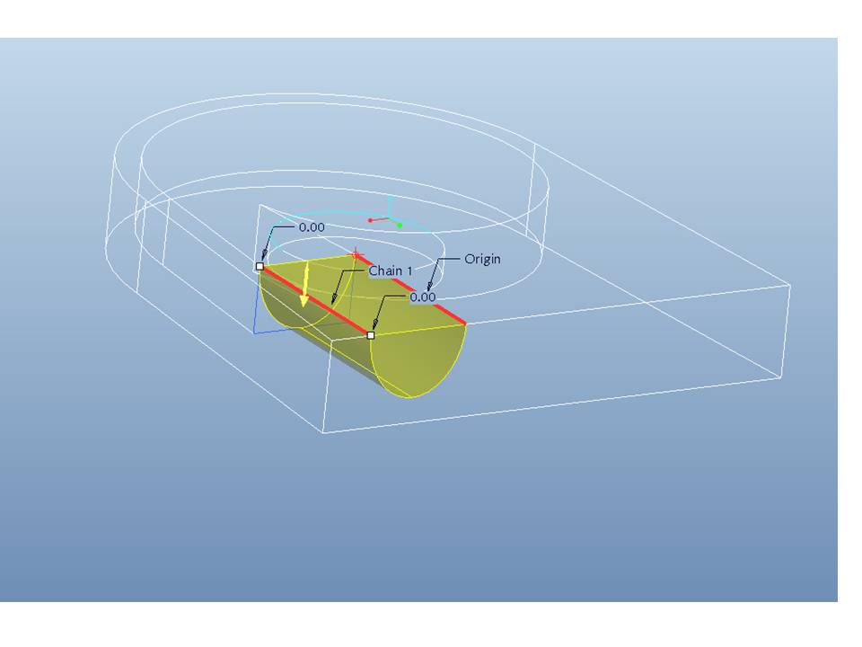
which of course is not variable section cut, but only one section.
This cannot give me a smooth trancation for rectangular to elliptical opening.
Any advise or amendment to my thought?
I am not very familiar with variable section sweeps but I think there might be an easy way that I just dont know.
Please help me , the soonest the better. I m in despair! 
Thanks,
Amanda
This thread is inactive and closed by the PTC Community Management Team. If you would like to provide a reply and re-open this thread, please notify the moderator and reference the thread. You may also use "Start a topic" button to ask a new question. Please be sure to include what version of the PTC product you are using so another community member knowledgeable about your version may be able to assist.
Solved! Go to Solution.
Labels:
- Labels:
-
Assembly Design
35 REPLIES 35
Mar 03, 2013
01:36 PM
- Mark as New
- Bookmark
- Subscribe
- Mute
- Subscribe to RSS Feed
- Permalink
- Notify Moderator
Please log in to access translation
Mar 03, 2013
01:36 PM
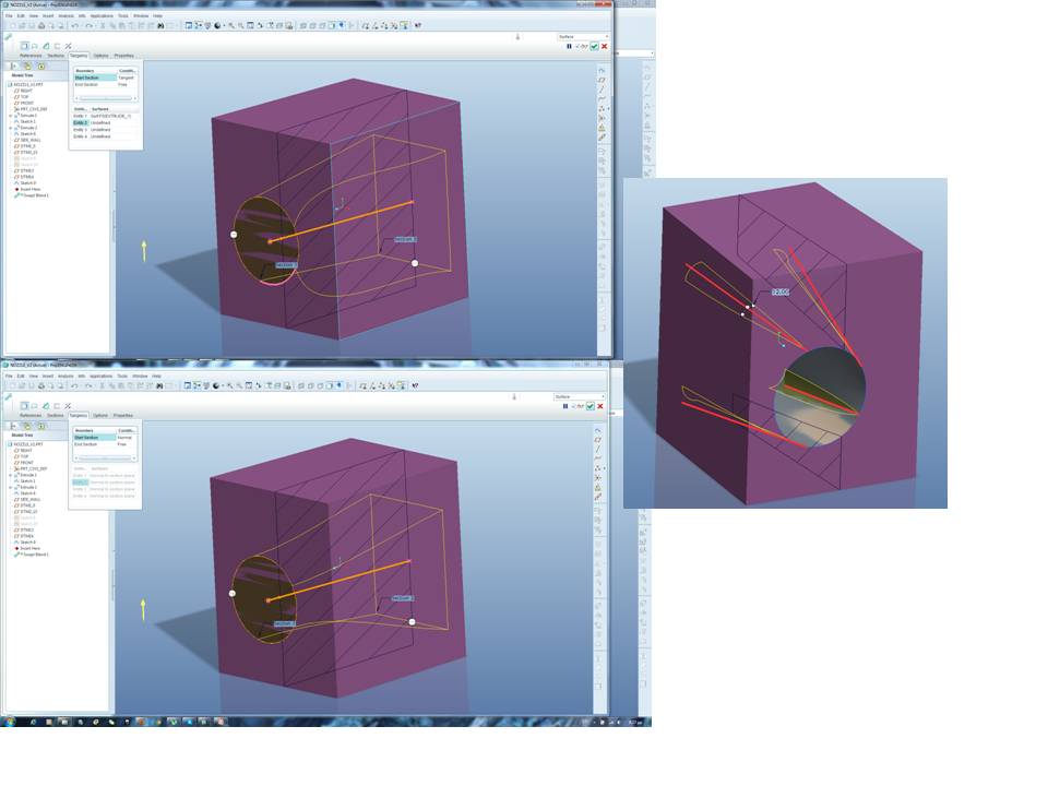
I have applied finally Swept Blend, with just 2 section at a 15cm transaction.
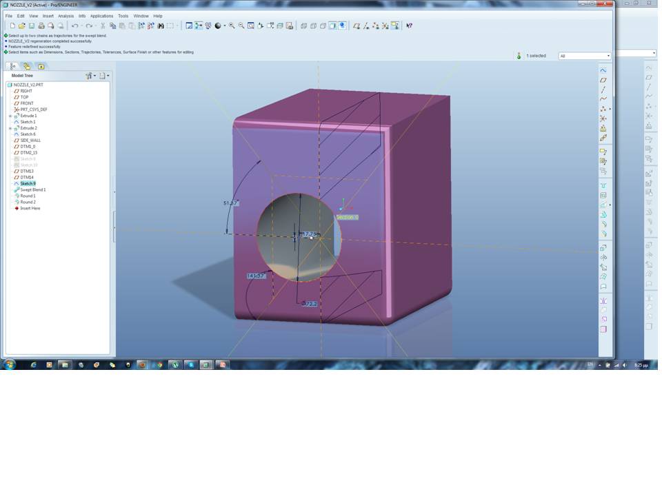
I chosen free ends for both sections, as tangent and normal created an unwanted curvature.
Then I applied a smooth radius.
I am not 100% satisfied yet. An other idea was to remove material gradually, every 10mm or 15mm distance, so as to have abt 15 sections and blend by pair. But that was worst, as the small distance create a strong twist of edges.
This is the final nozzle, as assembled to the basic turbine casing.
Thanks all for your advise.
Rgrds,
Amanda P.
Mar 03, 2013
02:07 PM
- Mark as New
- Bookmark
- Subscribe
- Mute
- Subscribe to RSS Feed
- Permalink
- Notify Moderator
Please log in to access translation
Mar 03, 2013
02:07 PM
That looks good... and simple as well.
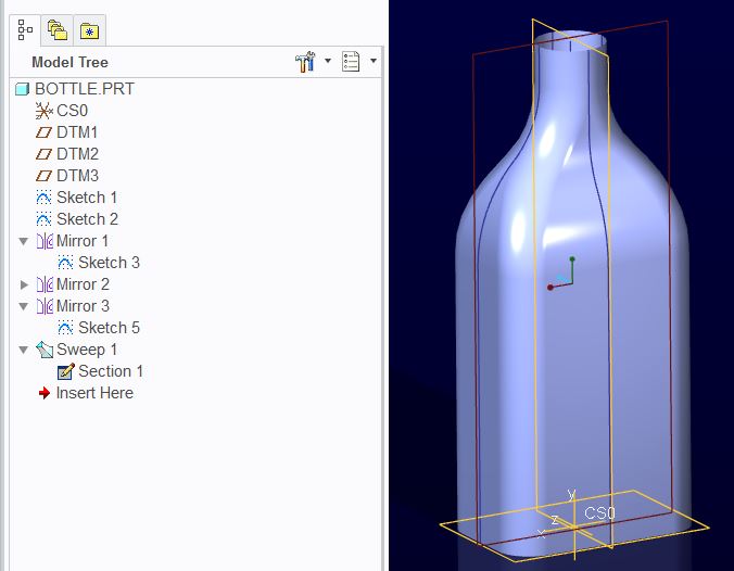
Often multiple sections lack the smoothness desired. If a particular path must be followed, guide curves in a variable section sweeps are more useful. One of PTC's knowledgebase examples is the bottle which is very similar to your "challenge".
Have you been following our discussion on the surface feature? I learned a lot about how to use the sweep feature in this discussion: http://communities.ptc.com/message/198441#198441
Mar 03, 2013
02:11 PM
- Mark as New
- Bookmark
- Subscribe
- Mute
- Subscribe to RSS Feed
- Permalink
- Notify Moderator
Please log in to access translation
Mar 03, 2013
02:11 PM
No I havent. I think it s time for me to go to surface modelling as well. I will follow and practise from this one discussion.
Further to all ptc discussions, does anybody knows a really worthy book to buy. I always prefer hard copies book for my library. I have none for Pro E, so i am thinking of buing, new or second hand. But I can find only junior level on the market.
Any suggestions?
Mar 04, 2013
05:32 AM
- Mark as New
- Bookmark
- Subscribe
- Mute
- Subscribe to RSS Feed
- Permalink
- Notify Moderator
Please log in to access translation
Mar 04, 2013
05:32 AM
So, do I understand this correctly?
The conclusion of the members of this forum is that there is no practical way to create a rectangular-to-round transition using the VSS feature, it has to be done using the swept blend feature.
I ask because I have repeatedly got the impression that the VSS is the Bees Knees, and that all those other, old-fashioned blends and things could really be dropped. I have never been able to convince myself that this is the case. I may, of course, have been getting hold of the wrong end of the stick all this time.
It would be great if someone would come up with a clever wheeze to disprove my hypothesis above.
It has always seemed to me that the Variable Section Sweep is a very useful tool, but that one thing it doesn't do well is produce models with a variable section...
There, that's put the cat among the pigeons!
Regards,
John
Mar 04, 2013
10:47 AM
- Mark as New
- Bookmark
- Subscribe
- Mute
- Subscribe to RSS Feed
- Permalink
- Notify Moderator
Please log in to access translation
Mar 04, 2013
10:47 AM
You've been listening to Frank, haven't you John 
The VSS is now just a button in the sweep command. In the other thread, we learned some very important awareness' about using the applied sections. once you know the rules, it is probably more powerful that one would think at 1st glance.
Yet, the blendtoo has some very capable options that really make a feature such as this quite appropriate. Not something you want to detail for machining, but if your model creates the tools, you can get some really nice blends between surfaces. Normal and tangent transitions makes the blend command easier to deal with than the VSS part of the sweep since it requires less data to manage.
Even some of the older "hidden" commands now considered "obsolete" or "less supported"... or whatever you want to label it, can be very powerful and useful when the job calls for it.
Awareness of what all the commands are capable of will let you know what tool will do the job best.
Mar 04, 2013
11:03 AM
- Mark as New
- Bookmark
- Subscribe
- Mute
- Subscribe to RSS Feed
- Permalink
- Notify Moderator
Please log in to access translation
Mar 04, 2013
11:03 AM
From what I've seen, the VSS will fail when a radius approaches infinity. I think a combination of VSS and swept blend would be the most powerful tool. To be able to use trajectories to move vertex's, and use blend vertex's, and even flatten a radius to a straight line would be awesome.
These things can be done with boundary blends in SOME cases, but not as easily since you need to make sure all 4 sides of your surface are defined.
As Antonius mentioned about a previous thread where you can get almost a C2 continuous surface, VSS's are extremely powerful tools, if a bit finicky, but if used correctly, can create some amazing shapes.
There are usually sever ways to do anything in Pro/E, but each, because of the math behind it, will give slightly different results. It's up t the Designer to choose which tool gives the desired geometry.
- « Previous
-
- 1
- 2
- Next »


