
Turn on suggestions
Auto-suggest helps you quickly narrow down your search results by suggesting possible matches as you type.
Showing results for
Please log in to access translation
Turn on suggestions
Auto-suggest helps you quickly narrow down your search results by suggesting possible matches as you type.
Showing results for
Community Tip - You can Bookmark boards, posts or articles that you'd like to access again easily! X
- Community
- Creo+ and Creo Parametric
- 3D Part & Assembly Design
- Re: How to measure change in dimension?
Translate the entire conversation x
Please log in to access translation
Options
- Subscribe to RSS Feed
- Mark Topic as New
- Mark Topic as Read
- Float this Topic for Current User
- Bookmark
- Subscribe
- Mute
- Printer Friendly Page
How to measure change in dimension?
May 11, 2016
05:50 AM
- Mark as New
- Bookmark
- Subscribe
- Mute
- Subscribe to RSS Feed
- Permalink
- Notify Moderator
Please log in to access translation
May 11, 2016
05:50 AM
How to measure change in dimension?
Hi,
Lets say I have cylinder and the inner pressure load is applied thru its wall, after analysis, I want to know what is the change in diameter of the cylinder wrt applied load, so that I can make my design better by changing its diameter.
Is there any way to measure it.
Thanks
Amit
This thread is inactive and closed by the PTC Community Management Team. If you would like to provide a reply and re-open this thread, please notify the moderator and reference the thread. You may also use "Start a topic" button to ask a new question. Please be sure to include what version of the PTC product you are using so another community member knowledgeable about your version may be able to assist.
Labels:
- Labels:
-
2D Drawing
26 REPLIES 26
May 11, 2016
05:59 AM
- Mark as New
- Bookmark
- Subscribe
- Mute
- Subscribe to RSS Feed
- Permalink
- Notify Moderator
Please log in to access translation
May 11, 2016
05:59 AM
You could just plot the displacement in the results; or for a more precise answer:
- Create a surface region on the outside
- Create a cylindrical coordinate system at the centre
- Create a custom measure for the maximum radial displacement over the surface region (relative to the cyl csys).
May 11, 2016
06:11 AM
- Mark as New
- Bookmark
- Subscribe
- Mute
- Subscribe to RSS Feed
- Permalink
- Notify Moderator
Please log in to access translation
May 11, 2016
06:11 AM
Thanks Jonathan for quick reply.
I am very new to the simulation, if you could help me by any medium which can demonstrate and simplify the above step would be much of a help.
I will try to attached the model for your reference.
Amit
May 11, 2016
08:11 AM
- Mark as New
- Bookmark
- Subscribe
- Mute
- Subscribe to RSS Feed
- Permalink
- Notify Moderator
Please log in to access translation
May 11, 2016
08:11 AM
All the steps are pretty straightforward... try looking them up in the help files, and post back with any specific questions if you get stuck.
May 12, 2016
04:37 AM
- Mark as New
- Bookmark
- Subscribe
- Mute
- Subscribe to RSS Feed
- Permalink
- Notify Moderator
Please log in to access translation
May 12, 2016
04:37 AM
I am struggling in the step of Creating a custom measure for the maximum radial displacement over the surface region (relative to the cyl csys).
Please guide. I could not found anything in help on this. Rather its leads to confusion 
May 12, 2016
05:43 AM
- Mark as New
- Bookmark
- Subscribe
- Mute
- Subscribe to RSS Feed
- Permalink
- Notify Moderator
Please log in to access translation
May 12, 2016
05:43 AM
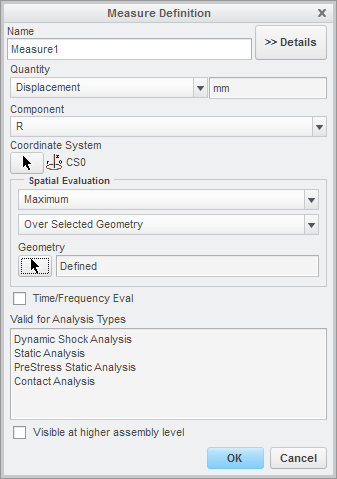
It looks like the option to select a coordinate system doesn't appear until you select Displacement, and then change from Magnitude to one of the components (X for example).
Then you can select the coordinate system, and the components become R, T, Z.
May 12, 2016
06:47 AM
- Mark as New
- Bookmark
- Subscribe
- Mute
- Subscribe to RSS Feed
- Permalink
- Notify Moderator
Please log in to access translation
May 12, 2016
06:47 AM
I tried that and it is working for me. But the result of the measures are very very negligible (i.e. 0.000685)
I wounder if I am heading in a right direction, because the value is very small which is not matching to my expectation.
Any suggestions please
May 12, 2016
06:52 AM
- Mark as New
- Bookmark
- Subscribe
- Mute
- Subscribe to RSS Feed
- Permalink
- Notify Moderator
Please log in to access translation
May 12, 2016
06:52 AM
What units are you working in? Do you have the correct values (including units) for pressure and for the material modulus?
Have you done a hand calculation to get an idea of the answer you should be expecting?
May 12, 2016
07:10 AM
- Mark as New
- Bookmark
- Subscribe
- Mute
- Subscribe to RSS Feed
- Permalink
- Notify Moderator
Please log in to access translation
May 12, 2016
07:10 AM
From the start I made myself correct with units and materials to use, I cross checked it, though.
I do not have any hand calculations done, but the real life failure occurred on the part make me speculate that the result is not correct.
Even, I am not sure that the values is the difference between the ID & OD.
May 12, 2016
07:26 AM
- Mark as New
- Bookmark
- Subscribe
- Mute
- Subscribe to RSS Feed
- Permalink
- Notify Moderator
Please log in to access translation
May 12, 2016
07:26 AM
Hmm - that doesn't seem to agree with the legend.
Try creating some displacement measures in Cartesian coordinates too - as the model is (essentially) axisymmetric, they should all agree.
On the red/green/cyan triad at the lower left, does it say 'R' next to the red axis? If so, that doesn't look right... You could also try creating measures for all three cylindrical directions (R, T, Z) just to check.
May 12, 2016
07:51 AM
- Mark as New
- Bookmark
- Subscribe
- Mute
- Subscribe to RSS Feed
- Permalink
- Notify Moderator
Please log in to access translation
May 12, 2016
07:51 AM
I tried with creating all the 3 measure but no luck...
Is it so difficult to measure a simple change in dimension of particular features!!
May 12, 2016
08:12 AM
- Mark as New
- Bookmark
- Subscribe
- Mute
- Subscribe to RSS Feed
- Permalink
- Notify Moderator
Please log in to access translation
May 12, 2016
08:12 AM
When you say "no luck", what exactly happened?
Also, what are your units of stress? I thought the numbers looked large, but are they MPa or Pa? In any case it looks like you have some very small holes and also sharp corners, so the high stresses may (will) be concentrations.
I've just opened your model, but the version you attached has no loads or constraints...
May 12, 2016
08:28 AM
- Mark as New
- Bookmark
- Subscribe
- Mute
- Subscribe to RSS Feed
- Permalink
- Notify Moderator
Please log in to access translation
May 12, 2016
08:28 AM
" No Luck" means values I derived are similar to what I got earlier.
My units are in Pascals i.e.784532 Pa. I have attached a fresh model with all loads and constraints
May 12, 2016
08:46 AM
- Mark as New
- Bookmark
- Subscribe
- Mute
- Subscribe to RSS Feed
- Permalink
- Notify Moderator
Please log in to access translation
May 12, 2016
08:46 AM
You appear to have applied a uniform pressure over the entire component - both inside and out. Are you expecting it to do anything at all? Are you trying to model HIPping (hot isostatic pressing)?
As a side comment, you've also rigidly fixed the ID - is it really constrained so that it cannot expand?
May 12, 2016
08:53 AM
- Mark as New
- Bookmark
- Subscribe
- Mute
- Subscribe to RSS Feed
- Permalink
- Notify Moderator
Please log in to access translation
May 12, 2016
08:53 AM
The load is applied only at the "OD" (not from inside).
I am not sure about the terminology of HIPping !
Yes, The inner ID is constraint so that it should not move and expand.
May 12, 2016
09:25 AM
- Mark as New
- Bookmark
- Subscribe
- Mute
- Subscribe to RSS Feed
- Permalink
- Notify Moderator
Please log in to access translation
May 12, 2016
09:25 AM
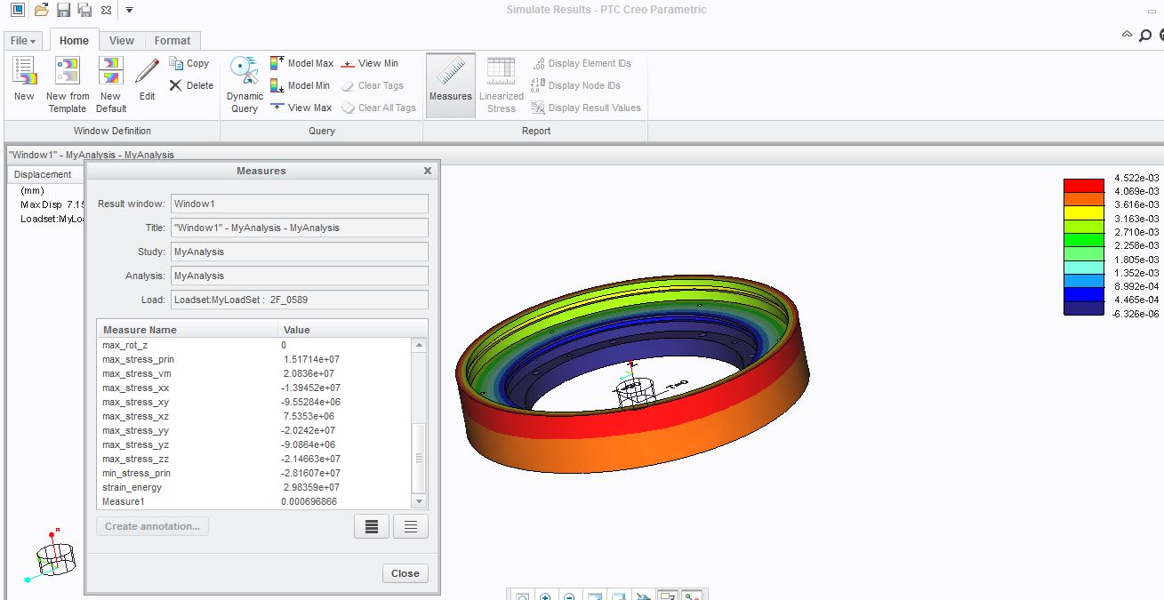
Check your pressure load carefully - on the model I copied from inside MyAnalysis, the pressure was applied to all surfaces.
If I correct that, and create three separate measures as I suggested, I get:
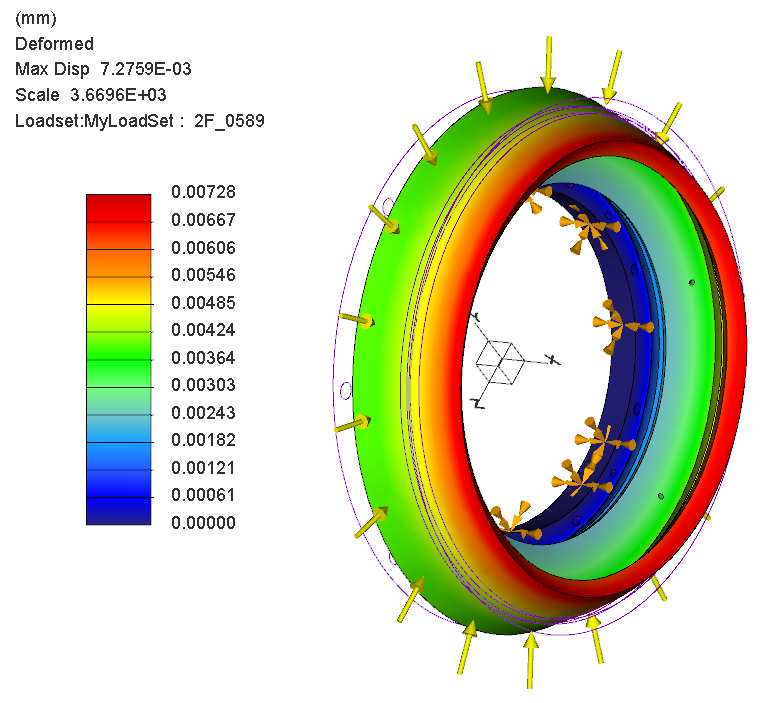
max_beam_bending: 0.000000e+00 max_beam_tensile: 0.000000e+00 max_beam_torsion: 0.000000e+00 max_beam_total: 0.000000e+00 max_disp_mag: 7.275905e-03 max_disp_x: 4.601114e-03 max_disp_y: -5.669041e-03 max_disp_z: -5.636576e-03 max_prin_mag*: -2.810408e+07 max_rot_mag: 0.000000e+00 max_rot_x: 0.000000e+00 max_rot_y: 0.000000e+00 max_rot_z: 0.000000e+00 max_stress_prin*: 1.505590e+07 max_stress_vm*: 2.128871e+07 max_stress_xx*: -1.336667e+07 max_stress_xy*: -8.836680e+06 max_stress_xz*: 7.782414e+06 max_stress_yy*: -2.057084e+07 max_stress_yz*: -9.368814e+06 max_stress_zz*: -2.245988e+07 min_stress_prin*: -2.810408e+07 strain_energy: 3.102561e+07 CylR: 7.059701e-04 CylT: 2.218392e-05 CylZ: 4.601114e-03
max_disp_x and CylZ agree, but the displacement you're looking for is max_disp_y or _z.
I must admit I don't know why CylR doesn't match these values, though...
Any ideas?
May 14, 2016
06:55 AM
- Mark as New
- Bookmark
- Subscribe
- Mute
- Subscribe to RSS Feed
- Permalink
- Notify Moderator
Please log in to access translation
May 14, 2016
06:55 AM
I did it and found the same results, But I what is the significance of the max_disp_x and CylZ values?
Does those value means that the ID of the part will deform/move -0.0046011 towards center of the part?
Could you please help me to understand those output !
May 16, 2016
04:03 AM
- Mark as New
- Bookmark
- Subscribe
- Mute
- Subscribe to RSS Feed
- Permalink
- Notify Moderator
Please log in to access translation
May 16, 2016
04:03 AM
Nope, max_disp_x is the maximum displacement in the x direction, which should be (and is) the same as the maximum displacement in the Z-direction (axis) of the cylindrical csys. This is the direction you're not interested in.
The direction you are interested in is the maximum (magnitude) in the other two directions, y and z in Cartesian. The built-in measures shown that this is around 5.6 microns (5.64/5.67). I'm baffled as to why the cylindrical measure didn't pick this up correctly; but we've found odd behaviours and units with cylindrical systems before.
However, I suspect that the real answer may be slightly more than this, as I don't see how you can constrain the ID completely rigidly - unless this is a polymer component and you're shrink-fitting it onto a steel rod...
The maximum total displacement magnitude, again from the built-in measures, is 7.28 microns... just as a check, sqrt(4.6^2 + 5.6^2) = 7.25 so this does add up correctly (assuming that the same point on the model has both the maximum radial and the maximum axial displacement).
In case you hadn't already realised, the list of measures I pasted above can be seen in the Status window both during and after a run; and is in fact contained in the .rpt file within the analysis folder. I often keep a copy of the .rpt for a finished analysis as it contains most of the useful information.
May 18, 2016
10:14 AM
- Mark as New
- Bookmark
- Subscribe
- Mute
- Subscribe to RSS Feed
- Permalink
- Notify Moderator
Please log in to access translation
May 18, 2016
10:14 AM
Jonathan,
It took a moment but I see why.
Using the model from the MyAnalysis directory and editing the pressure load to be on the outside only I get exactly the same results as your image.
This is the rotations causing different subtended distances Z&Y Cartesian to the radial movement and inconsistent measurement location.
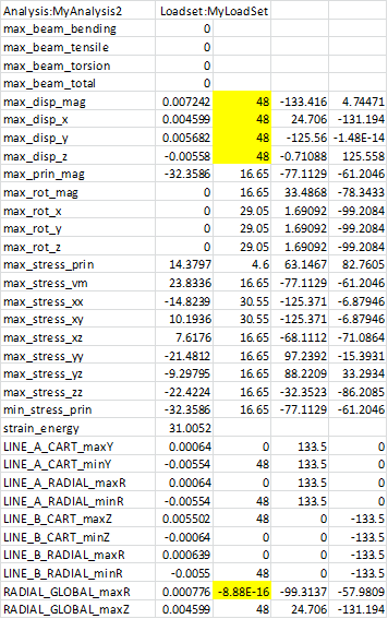
I added edges to the model to and measured as follows :
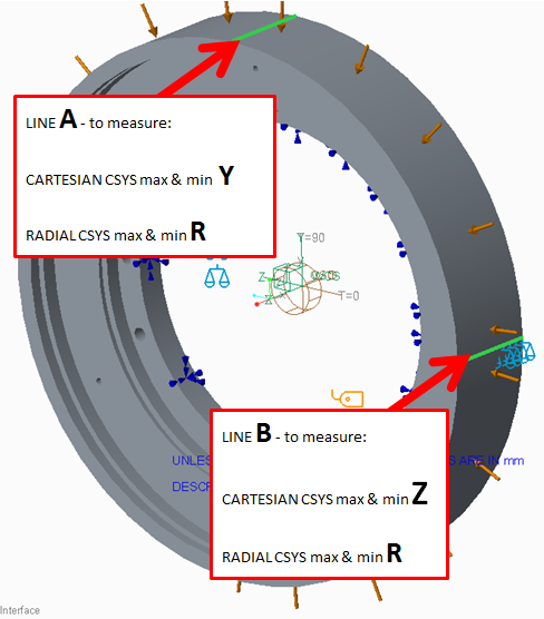
I got the following :
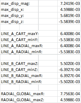
max and min Cartesian measures required rather than more lines (symmetry, and I didn't know which way the radial measure would go). Seems consistent.
The max_disp_x = RADIAL_GLOBAL_MAX_Z as you found.
The max_disp_y & z nearly equal to each other and don't equal RADIAL_GLOBAL_maxR as you found. These are affected by rotations and their locations not consistent as follows:
All seems good.
To Amit's questions ...
This is a 270mm diameter steel ring with a rim that is 8mm thick and a substantial hub.
The external pressure of 0.8MPa is small and will do little. The displacements are tiny approaching un-measurable.
NB, the CTE in the material definition should be 16e-6 mm/mm/degC, it is in as '16'.
Model attached. I changed the units of the model to mmNS.
It would be interesting to know where this fails.
atb
May 19, 2016
03:38 AM
- Mark as New
- Bookmark
- Subscribe
- Mute
- Subscribe to RSS Feed
- Permalink
- Notify Moderator
Please log in to access translation
May 19, 2016
03:38 AM
Ah, thanks Charles - good investigation.
In fact, I think you've picked up on my main error, which was simply that I should have been looking for MinR, not max, as the displacement is expected to be inwards - my CylR measure presumably picked up the tiny movement outwards at the end closer to the hub, equivalent to your MaxY and MinZ.
May 19, 2016
04:14 AM
- Mark as New
- Bookmark
- Subscribe
- Mute
- Subscribe to RSS Feed
- Permalink
- Notify Moderator
Please log in to access translation
May 19, 2016
04:14 AM
It was either that or do some work.
It piqued my interest as measure outputs are fundamental bread and butter outputs and are used as part of QA.
After looking at Matthew Parmenteri's question
RPT file and displacement plot have different values
I now trust the system measures even less and need to poke around this one a bit more.
Charles
May 26, 2016
07:30 AM
- Mark as New
- Bookmark
- Subscribe
- Mute
- Subscribe to RSS Feed
- Permalink
- Notify Moderator
Please log in to access translation
May 26, 2016
07:30 AM
Thanks Charles...It seems to a very detailed investigation about the part.
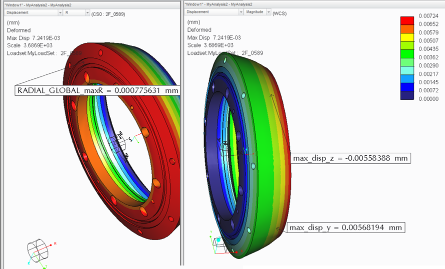
But my intension was very simple. I just wanted to know "The change in dia or deflection on the wall (highlighted in image)" to that particular load.
For me all those assumptions are very difficult to understand. But overall I could understand that the stress developed are very high and the load does affect very little change in respective direction(which is negligible).
May 26, 2016
08:17 AM
- Mark as New
- Bookmark
- Subscribe
- Mute
- Subscribe to RSS Feed
- Permalink
- Notify Moderator
Please log in to access translation
May 26, 2016
08:17 AM
Amit,
Can you confirm the value of stress that concerns you and its location?
My memory of the results I got was in the order of 20MPa. This is small.
Patrick, I know this contradicts your conclusions but I got the same displacement as Jonathan.
The radial displacement of the external surface I got was measureable in microns. This is small.
The internal surface diameter cannot change as it is fixed.
Something's a bit strange and I am concerned one, both or all of us have unit problems.
Some statistics from the model you uploaded for checking, I have highlighted the first one for special attention:
- Pressure load is applied to the external surface only = 784532 Pa or 0.78 MPa
- External surface diameter = 267 mm
- External surface width = 48 mm
- Rim internal diameter = 251.12 mm
- Internal surface FULLY fixed
- Internal hub diameter = 170.4
- Hub thickness between 15 and 30mm
- Material = STEEL (approximately) with E=205GPa, nu=0.25
Ignoring fully fixed internal surface, Lame says Hoop on the internal surface will be about -14 MPa
Radial stress can go no higher than the applied pressure.
Dimensions seem 'reasonable' for something resembling a brake drum.
Are you sure your pressure is correct? 0.78MPa is very small please check this.
What is the application?
Regards
May 12, 2016
07:45 AM
- Mark as New
- Bookmark
- Subscribe
- Mute
- Subscribe to RSS Feed
- Permalink
- Notify Moderator
Please log in to access translation
May 12, 2016
07:45 AM
Your stress is really high. It's important to note that you are probably not using material plasticity in your model, but in reality plasticity would certainly occur with these high stresses.
May 12, 2016
07:54 AM
- Mark as New
- Bookmark
- Subscribe
- Mute
- Subscribe to RSS Feed
- Permalink
- Notify Moderator
Please log in to access translation
May 12, 2016
07:54 AM
I am sure you guys must be experts in the simulation but, I am not sure about those stress. I am not from simulation background.
I goal is very simple. I am to measure the change in ID & OD of a circular object when certain load/pressure is applied to it.
May 12, 2016
08:24 AM
- Mark as New
- Bookmark
- Subscribe
- Mute
- Subscribe to RSS Feed
- Permalink
- Notify Moderator
Please log in to access translation
May 12, 2016
08:24 AM
You can do a simple hand calculation to get a first estimate, and check if your FE analysis results are in the same order of magnitude.
I'm sure there is a suitable formula in Roark's for your case 
May 12, 2016
06:52 AM
- Mark as New
- Bookmark
- Subscribe
- Mute
- Subscribe to RSS Feed
- Permalink
- Notify Moderator
Please log in to access translation
May 12, 2016
06:52 AM
Check which units you are using, and whether the material properties and loads are in correspondance with your chosen unit system.
(This is the number one mistake made by beginning Mechanica users, PTC should really find a fix for it.)


