Community Tip - When posting, your subject should be specific and summarize your question. Here are some additional tips on asking a great question. X
- Community
- Creo+ and Creo Parametric
- 3D Part & Assembly Design
- IGES assembly not displaying and not showing parts...
- Subscribe to RSS Feed
- Mark Topic as New
- Mark Topic as Read
- Float this Topic for Current User
- Bookmark
- Subscribe
- Mute
- Printer Friendly Page
IGES assembly not displaying and not showing parts in tree
- Mark as New
- Bookmark
- Subscribe
- Mute
- Subscribe to RSS Feed
- Permalink
- Notify Moderator
IGES assembly not displaying and not showing parts in tree
Using Pro/E 5 Wildfire
I saved an assembly as IGES (.igs) with all the parts using the "save as copy" method.
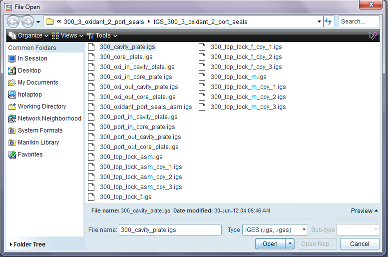
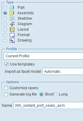
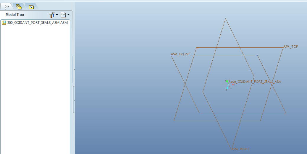
To test to see if the machinist will be able to open it, I tried to open the main assembly file (as an assembly) and there is nothing displayed in the main window and the parts of the assembly are not listed in the file tree. I heard that the model could be tiny if there is a unit difference but I can not zoom in and find anything. I've tried all sorts of different settings in the open file options window but nothing is working. The following is some screen shots:


This thread is inactive and closed by the PTC Community Management Team. If you would like to provide a reply and re-open this thread, please notify the moderator and reference the thread. You may also use "Start a topic" button to ask a new question. Please be sure to include what version of the PTC product you are using so another community member knowledgeable about your version may be able to assist.
- Labels:
-
Assembly Design
- Mark as New
- Bookmark
- Subscribe
- Mute
- Subscribe to RSS Feed
- Permalink
- Notify Moderator
Hello Andrey!
Can u tell us if there is any error message? For now try to see in tree display settings if u have features or components hidden from tree because i see there is datums in assembly but not visible in tree. See in layers if components are hidden.
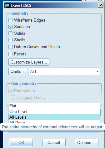
I now took a last look in the files you have in your iges directory and my guess is that proe will only open all components if u have saves the iges file with the option "All levels" since All parts option will export files individual i mean you only get the features made in assembly.
- Mark as New
- Bookmark
- Subscribe
- Mute
- Subscribe to RSS Feed
- Permalink
- Notify Moderator
Ok I've checked and there is no error message, and all the layers are visable, all features and all components are visable, and anything else I could check to see if it's hidden turned up nothing.
Very interesting point you have being "All parts option will export files individual i mean you only get the features made in assembly". So that is strange. So since I made the parts outside the assembly and then imported them in and constrained them together that's why they are not being displayed. If I had created the parts inside the assembly screen then they would. Well if that is true that is very strange why they made it work like that but oh well.
Ok so I did what you suggested by saving "All Levels" and tried both "Surfaces" and "Solids" instead and that works -kind of. All the parts are in the model tree and displayed when I open the IGES file. But I have sub assemblies that do not appear in the model tree or in the display. In this example I have a simple sub assembly of just 2 parts and there are 4 instances of it that are constrained to the main assembly. Any ideas of why?
- Mark as New
- Bookmark
- Subscribe
- Mute
- Subscribe to RSS Feed
- Permalink
- Notify Moderator
" If I had created the parts inside the assembly screen then they would. Well if that is true that is very strange why they made it work like that but oh well."
No, that is not true, there is another problem there, can you try a step file instead?
- Mark as New
- Bookmark
- Subscribe
- Mute
- Subscribe to RSS Feed
- Permalink
- Notify Moderator
Yes I have done saving as a STEP (.stp) and that works with all the parts and the sub assemblies (all the colors are gone but I can live with that).
But I must send IGES to the machinist as they are specifically requesting that with the STEP files.
Thx btw
- Mark as New
- Bookmark
- Subscribe
- Mute
- Subscribe to RSS Feed
- Permalink
- Notify Moderator
step_export_format ap214_cd
put this in your config file to send step files with color.
I really don't know why your iges file don't open with the full tree and all assemblys on the tree because that problem never happened to me and i make more than 20 iges per day, i will put here my config pro iges parameters for you to try if you want.
iges_out_assembly_default_mode all_parts
iges_out_mil_d_28000 NO
iges_out_spl_crvs_as_126 YES
iges_out_spl_srfs_as_128 YES
iges_out_trim_curve_deviation default
iges_out_trim_xyz YES
iges_out_trm_srfs_as_143 NO
- Mark as New
- Bookmark
- Subscribe
- Mute
- Subscribe to RSS Feed
- Permalink
- Notify Moderator
Thanks for the help. The config for the color setting for .stp works. The export "all levels" option seems to work and I get all the parts and the tree is correct so I'll just use that.
I have put in the other config settings as well.
Maybe you have solved this other problem but if not i will make another thread.
The machinist is using MasterCam 9 and we can not find an exported from ProE5 format that will work.
He says that they use IGES most of the time and it works well. However when opening the IGES files I send in using both export formats conditions of "Solids, Shells, Datums, Facets" and "Surfaces, (no Wireframe Edges)" he says the files will not open properly. I tried to get more info out of him of just what was going on but he seems a bit confused so I'm trying to get a copy of MasterCam 9 and test it out myself as see. So have you come across this kind of problem and have a possible solution?
I've also send him STEP and he says it takes a long time to build and there are strange "noodle" forms around features such as holes and other curves.
I've also send him a Solidworks format that was derrived from the IGES and he says those work but there are many fragments of surfaces and he can not separate the parts as a whole.
- Mark as New
- Bookmark
- Subscribe
- Mute
- Subscribe to RSS Feed
- Permalink
- Notify Moderator
Hi Andrey...
Seems like your problem isn't Pro/E... it's your machinist!
I've worked with many machinists using MasterCam and they're living in the dark ages. Your machinist should be able to use STEP... IGES is really starting to show it's age. STEP isn't perfect either but at least it's tried to stay relevant.
But since your machinist insists on IGES... the other question that comes to mind is... why are you sending him assemblies? If he's a machinist, he's making parts. Why send him a conglomeration of components as an assembly? Why not send him the individual components in separate files? Send him an assembly in STEP format for reference so he sees how everything goes together. But he could use the IGES files of the individual parts for his work in MasterCam?
Maybe I'm missing something but it seems like you're jumping through hoops to solve a problem the machinist is having... that he's partially causing! You have an assembly of parts and he's struggling to untangle them and machine them from the STEP file. It just seems sort of odd to me. Then again, maybe I just don't understand the application.


