Community Tip - Have a PTC product question you need answered fast? Chances are someone has asked it before. Learn about the community search. X
- Community
- Creo+ and Creo Parametric
- 3D Part & Assembly Design
- Re: Importing Iges/Step files into Creo Parametric...
- Subscribe to RSS Feed
- Mark Topic as New
- Mark Topic as Read
- Float this Topic for Current User
- Bookmark
- Subscribe
- Mute
- Printer Friendly Page
Importing Iges/Step files into Creo Parametric 2.0 for Editing
- Mark as New
- Bookmark
- Subscribe
- Mute
- Subscribe to RSS Feed
- Permalink
- Notify Moderator
Importing Iges/Step files into Creo Parametric 2.0 for Editing
Good Morning,
I have recently started using Creo Parametric 2.0. I am trying to import iges and step files into Creo and edit the features. Everytime I open the iges or step file in Creo I am unable to measure between two surfaces much less change any features on any of the parts within the assembly. Is there another way to import these files for editing purposes?
Thanks,
Robert
This thread is inactive and closed by the PTC Community Management Team. If you would like to provide a reply and re-open this thread, please notify the moderator and reference the thread. You may also use "Start a topic" button to ask a new question. Please be sure to include what version of the PTC product you are using so another community member knowledgeable about your version may be able to assist.
- Labels:
-
Data Exchange
- Mark as New
- Bookmark
- Subscribe
- Mute
- Subscribe to RSS Feed
- Permalink
- Notify Moderator
Right, you can only access .sec files while sketcher is open using the all files filter under the get data drop down.
- Mark as New
- Bookmark
- Subscribe
- Mute
- Subscribe to RSS Feed
- Permalink
- Notify Moderator
There are many ways to do what you want, yet when you have FMX.
I'd get rid of that line in the hole, and place a datum axis there instead. FMX Move can move datums along with the geometry. Also FMX Mirror can mirror datums, which is pretty good.
For starters it's best to watch these:
http://www.ptc.com/appserver/wcms/events/online.jsp?&im_dbkey=158918&icg_dbkey=142
http://www.ptc.com/appserver/wcms/events/online.jsp?&im_dbkey=158975&icg_dbkey=142
- Mark as New
- Bookmark
- Subscribe
- Mute
- Subscribe to RSS Feed
- Permalink
- Notify Moderator
Are they importing and solid, or are they broken quilts? The first step is fixing them to make them solid, if they are not.
I have had a ton of good luck with the flexible modeling. Even imports where I adjusted feaures that had a bunch of radii updated perfectly.
It also depends on what (and how many features) you want to edit.
- Mark as New
- Bookmark
- Subscribe
- Mute
- Subscribe to RSS Feed
- Permalink
- Notify Moderator
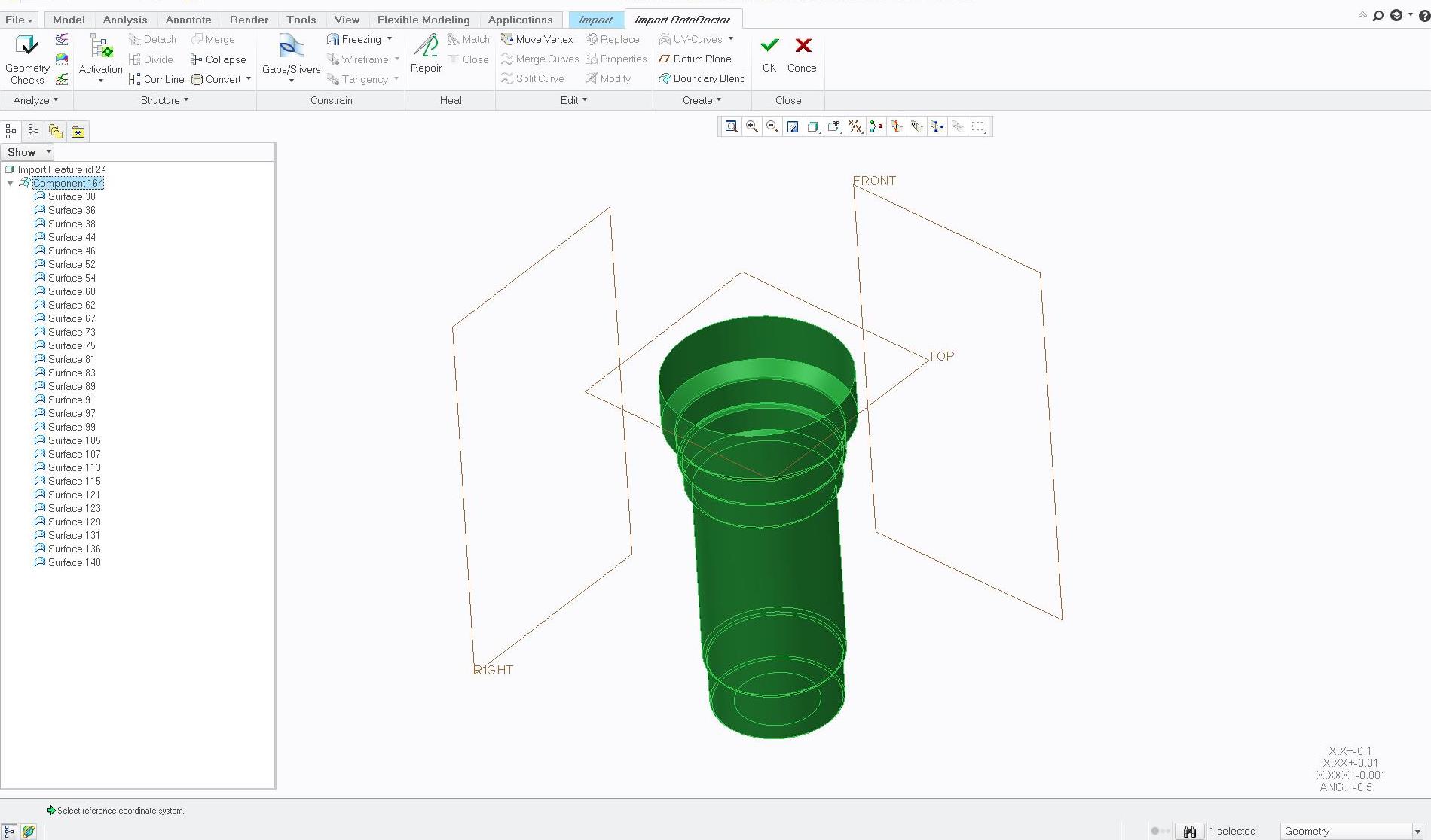
I highlighted Component 164 after removing the block around the hole. Selected Repair, checked Repair Tangency and Ok. Is that what you mean by making it a solid? 
- Mark as New
- Bookmark
- Subscribe
- Mute
- Subscribe to RSS Feed
- Permalink
- Notify Moderator
No, using this method, I would exit out of IDD mode and then draw a surface over the top opening, then merge, then solidify. If the bottom is open (can not quite tell in the picture), then you have to close it with a surface also and merge it before the solidify.
Again, this is just one of the many methods of using this geometry, and in my opinion usually deciding how to use the geometry is trying to have some thought on how you are going to need to modify it in the future, which is how I tend to do all my modeling anyway.
- « Previous
-
- 1
- 2
- Next »


