
Turn on suggestions
Auto-suggest helps you quickly narrow down your search results by suggesting possible matches as you type.
Showing results for
Please log in to access translation
Turn on suggestions
Auto-suggest helps you quickly narrow down your search results by suggesting possible matches as you type.
Showing results for
- Community
- Creo+ and Creo Parametric
- 3D Part & Assembly Design
- Re: Incomplete Fastener surface regions
Translate the entire conversation x
Please log in to access translation
Options
- Subscribe to RSS Feed
- Mark Topic as New
- Mark Topic as Read
- Float this Topic for Current User
- Bookmark
- Subscribe
- Mute
- Printer Friendly Page
Incomplete Fastener surface regions
Apr 26, 2017
12:46 PM
- Mark as New
- Bookmark
- Subscribe
- Mute
- Subscribe to RSS Feed
- Permalink
- Notify Moderator
Please log in to access translation
Apr 26, 2017
12:46 PM
Incomplete Fastener surface regions
Hello,
Has anyone seen this before?
The fasteners have incomplete surface regions.
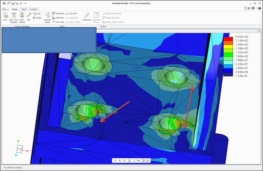
The surface regions are complete on the other side and at the contact between the components.
As can be seen in the image, there is nothing spectacularly complex about the geometry (else I couldn't model it).
ttfn
Labels:
- Labels:
-
Surfacing
7 REPLIES 7
Apr 26, 2017
01:53 PM
- Mark as New
- Bookmark
- Subscribe
- Mute
- Subscribe to RSS Feed
- Permalink
- Notify Moderator
Please log in to access translation
Apr 26, 2017
01:53 PM
Hi Charles,
no, I never saw something like that - for sure a bug. Important to fix since the element surfaces within the bolt- and nut head diameters are needed to fix the weighted links of the bolt spring ends correctly. If the (incomplete) circles you show are the separation test diamaters, then they are important because only then the separation test springs for the linearized fastener feature formulation can be attached correctly. For more details, see my presentation about bolt analysis in simulate in my blog (Analysis of Bolted Connections in Creo Simulate - Theory, Software Functionality and Application Examples)
If the circles you show are the separation test circles and you use nonlinear contact (not the linear formulation with fix separation), you may ignore this problem. But for all other cases these circles must be complete. You may check how the weighted links are fixed by looking into the TERFILE in the engine study directory; you have to set environment variable "PRINT_TERFILE" to "ON" for this.
B.t.w.: I think these circles are internally no surfaces regions, just hard curves. You may check in indepenendet mode if you still can use Creo 2 (Creo 3 does not support it any longer :-(, now sometimes it is hard to really see what simulate makes internally.
Please file an SPR for this and post number and actual state of it. Many Thanks!
Best regards,
Roland
Apr 26, 2017
03:46 PM
- Mark as New
- Bookmark
- Subscribe
- Mute
- Subscribe to RSS Feed
- Permalink
- Notify Moderator
Please log in to access translation
Apr 26, 2017
03:46 PM
Hi Roland,
I got anomalous fastener tensions which is why I looked.
The (almost) circles are under the head and are not separation test diameters.
I always use contact anyway.
The other end (nut) seems fine as do the separation test diameters even though they are unused.
I always thought separation test diameters were surface regions; so the weighted link goes to the hard curve and not an annular surface. Wouldn't this give us locally high stress on the curve?
This model is Creo 3 so cannot look in legacy.
I set the environment variable. Where abouts is the TERFILE written?
I will file an SPR tomorrow.
Thanks
Charles
Apr 26, 2017
04:11 PM
- Mark as New
- Bookmark
- Subscribe
- Mute
- Subscribe to RSS Feed
- Permalink
- Notify Moderator
Please log in to access translation
Apr 26, 2017
04:11 PM
Hi Charles,
the weighted links go to all element faces within the hard curve, so it is a circular surface that is connected: No problem regarding singularities. I guess using this circle was easier to code since you do not need surface splitting with new IDs from Pro/E, but I don't know.
The TERFILE (file extension *.ter) is an ASCII-file showing nodes, elements, weighted links etc., a bit like a classical input deck of an h-FEM-code. With help of it you may be able to check to what element faces of the incomplete fastener head diameter the weighted links are connected to, but it is no nice work to look for this, especially without legacy... I think it was written into the lower directory of the study directory (I don't remember exactly since I did not use it for a longer time). You may need an additional engine file in the study directory with more information to find it out in detail (the .neu-file with h-nodes Information), but you have to find it out. I remember it works since I tried this many years ago with a model giving unexpected results, but now I have to try it out again, too.
Best,
Roland
Apr 27, 2017
08:29 AM
- Mark as New
- Bookmark
- Subscribe
- Mute
- Subscribe to RSS Feed
- Permalink
- Notify Moderator
Please log in to access translation
Apr 27, 2017
08:29 AM
Roland,
I noticed that when one meshes before a run the problem does not occur.
If the mesh is created at run time the problem appears.
bfn
Charles
Apr 27, 2017
10:37 AM
- Mark as New
- Bookmark
- Subscribe
- Mute
- Subscribe to RSS Feed
- Permalink
- Notify Moderator
Please log in to access translation
Apr 27, 2017
10:37 AM
I have opened a call but need to sort out NDA.
will feedback when there is something to tell.
C
Apr 27, 2017
11:19 AM
- Mark as New
- Bookmark
- Subscribe
- Mute
- Subscribe to RSS Feed
- Permalink
- Notify Moderator
Please log in to access translation
Apr 27, 2017
11:19 AM
Nope. Haven't had the time. Running in a different date code is on the list.
and as the issue is more of an annoyance in this case I can get on but it will be good to know the reason.
Also I haven't tried
- mesh refinements
- Meshing, saving the mesh and calling it at run time
- Looking at the TER file
The geometry is from Solidworks. Perhaps there is something odd with the translation?
Thanks
Apr 28, 2017
05:16 AM
- Mark as New
- Bookmark
- Subscribe
- Mute
- Subscribe to RSS Feed
- Permalink
- Notify Moderator
Please log in to access translation
Apr 28, 2017
05:16 AM
Steven,
They are flat, axes are aligned


