
Turn on suggestions
Auto-suggest helps you quickly narrow down your search results by suggesting possible matches as you type.
Showing results for
Please log in to access translation
Turn on suggestions
Auto-suggest helps you quickly narrow down your search results by suggesting possible matches as you type.
Showing results for
Community Tip - Have a PTC product question you need answered fast? Chances are someone has asked it before. Learn about the community search. X
- Community
- Creo+ and Creo Parametric
- 3D Part & Assembly Design
- Re: Inconsistent assemblies when no ground
Translate the entire conversation x
Please log in to access translation
Options
- Subscribe to RSS Feed
- Mark Topic as New
- Mark Topic as Read
- Float this Topic for Current User
- Bookmark
- Subscribe
- Mute
- Printer Friendly Page
Inconsistent assemblies when no ground
Mar 09, 2015
03:46 AM
- Mark as New
- Bookmark
- Subscribe
- Mute
- Subscribe to RSS Feed
- Permalink
- Notify Moderator
Please log in to access translation
Mar 09, 2015
03:46 AM
Inconsistent assemblies when no ground
I'm trying to make a ball bearing using the Pin assembly constraint
Sometimes I need the internal runner to spin, and other times the outer runner to spin, therefore, I cannot make one or another Default.
If I make it default, I get "You may not drag a model belonging to the ground body"
If I leave it Automatic, mechanica cries bricks when I try to put it on an assembly
(And I don't like the squares between the icon and the name of the part on the model tree)
It's not only the bearing.
Sometimes I make a whole arbor loose so I can make it a pin on a third assembly
There's got to be a way to overcome this
This thread is inactive and closed by the PTC Community Management Team. If you would like to provide a reply and re-open this thread, please notify the moderator and reference the thread. You may also use "Start a topic" button to ask a new question. Please be sure to include what version of the PTC product you are using so another community member knowledgeable about your version may be able to assist.
Labels:
- Labels:
-
Assembly Design
5 REPLIES 5
Mar 09, 2015
09:54 AM
- Mark as New
- Bookmark
- Subscribe
- Mute
- Subscribe to RSS Feed
- Permalink
- Notify Moderator
Please log in to access translation
Mar 09, 2015
09:54 AM
You need to have a fixed ground in your assembly, but that does not need to be a part. I have not tried this, but I would thing that you can create an assembly axis and use the pin connection on both components to the assembly axis and an assembly plane. Then both would be free to spin.
When placed in a higher level assembly, you would then fix either the inner or outer component to other parts in the assy as needed.
Mar 09, 2015
12:47 PM
- Mark as New
- Bookmark
- Subscribe
- Mute
- Subscribe to RSS Feed
- Permalink
- Notify Moderator
Please log in to access translation
Mar 09, 2015
12:47 PM
Your logic is perfect, but Creo is cheat-resistant
If I fix (Fix constraint) the object on the datums (if that's what you suggested), creo assumes that the object is the ground.
If I Pin the object using the datums, the not-well-constrained square appears between the icon and the name of the part and subparts on the model tree.
I will test this assembly on the bigger assembly, but I really think we are back to squat.
Mar 09, 2015
10:50 PM
- Mark as New
- Bookmark
- Subscribe
- Mute
- Subscribe to RSS Feed
- Permalink
- Notify Moderator
Please log in to access translation
Mar 09, 2015
10:50 PM

I CAN make the inner race default. If I attach that race to an arbor (rigid constraints, not pin - just as expected in real life), and the arbor spins, the bearing will work normally: the inner will follow the arbor, and the outer will be fixed.
I CANNOT do the above in a reverse order: Put the bearing somewhere, attached by the outer racer (which is pin), and After, attach the arbor to the inner. No: The arbor must hold the bearing.
Still looking for a way to make everything Not default AND consistent.
Apr 01, 2015
06:39 PM
- Mark as New
- Bookmark
- Subscribe
- Mute
- Subscribe to RSS Feed
- Permalink
- Notify Moderator
Please log in to access translation
Apr 01, 2015
06:39 PM
Can you try this ::
- assuming bearing is assembly itself, add default datums (3 planes) and create Axes
- constrain inner runner by Pin to assembly datums solely
- constrain outer runner by Pin to assembly datums solely (not referencing inner runner at all)
at this point, both rings should rotate independently.
Now when you add this bearing.asm to higher level assembly - be sure to only use bearing.asm datums (planes + axes) for placement. Hope this way both rings will continue rotate freely.
Pls let me know if this resolves the problem,
- Vlad
Apr 01, 2015
10:58 PM
- Mark as New
- Bookmark
- Subscribe
- Mute
- Subscribe to RSS Feed
- Permalink
- Notify Moderator
Please log in to access translation
Apr 01, 2015
10:58 PM
Thanks for the answer, Vlad
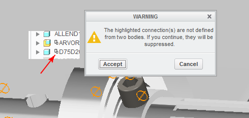
Performed the changes, but results were not different. The warning message from my first post still appears.
(Before the change, apart from the inner race (which is the first piece), all parts were pinned to the inner racer, instead of the assembly datums)
The mechanisms involving this bearing work fine. But I'm having a hard time to make things like gears.
This problem can be seen on a bigger picture.
If you find interest on this subject, you might look at my other thread, which involves this bearing.
Unable to make a gear
Maybe resolving that problem might resolve this one.


