Community Tip - New to the community? Learn how to post a question and get help from PTC and industry experts! X
- Community
- Creo+ and Creo Parametric
- 3D Part & Assembly Design
- Re: Is There A Round Feature?
- Subscribe to RSS Feed
- Mark Topic as New
- Mark Topic as Read
- Float this Topic for Current User
- Bookmark
- Subscribe
- Mute
- Printer Friendly Page
Is There A Round Feature?
- Mark as New
- Bookmark
- Subscribe
- Mute
- Subscribe to RSS Feed
- Permalink
- Notify Moderator
Is There A Round Feature?
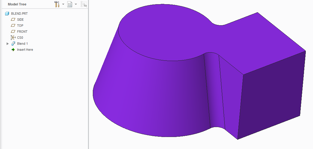
We come across this issue every once in awhile in our Wire EDM Department. The wire needs a straight line radius because the wire should not bend.
Is there a round feature that will give us a point to point constant round between these two primitives.
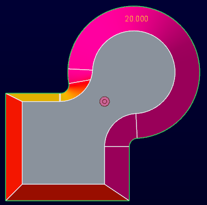
A cone being intersected by a tapered cube.
When we add a constant round the resulting (long) edges of the round become bent.
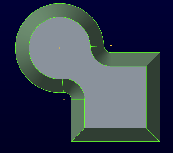
When looking from the top they look like this.
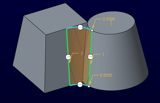
Here I created a boundary blend (yellow edges) between the upper cure and the lower cure (short edges of the round) to shot what result we are looking for. You can clearly see the bend in the long edges.
Is there a round feature that will give me the straight long edges of the round. Or, is this just impossible.
Thanks in advance for your help.
Dan
This thread is inactive and closed by the PTC Community Management Team. If you would like to provide a reply and re-open this thread, please notify the moderator and reference the thread. You may also use "Start a topic" button to ask a new question. Please be sure to include what version of the PTC product you are using so another community member knowledgeable about your version may be able to assist.
Solved! Go to Solution.
- Labels:
-
General
Accepted Solutions
- Mark as New
- Bookmark
- Subscribe
- Mute
- Subscribe to RSS Feed
- Permalink
- Notify Moderator
- Mark as New
- Bookmark
- Subscribe
- Mute
- Subscribe to RSS Feed
- Permalink
- Notify Moderator
Your first picture looks like the intersection between the cone and the tapered square is curved. If it's curved, the radius will be curved too.
- Mark as New
- Bookmark
- Subscribe
- Mute
- Subscribe to RSS Feed
- Permalink
- Notify Moderator
I agree - the intersection between a cone and a plane that is not through the axis of the cone is a curve.
- Mark as New
- Bookmark
- Subscribe
- Mute
- Subscribe to RSS Feed
- Permalink
- Notify Moderator
- Mark as New
- Bookmark
- Subscribe
- Mute
- Subscribe to RSS Feed
- Permalink
- Notify Moderator
Thanks for the replies. This is how we currently get around the issue, with a boundary blend surface (a lot of features). I was checking with the community to see if maybe there was a new type of round (maybe chordal) that would replicate this behavior.
Thanks again,
Dan
- Mark as New
- Bookmark
- Subscribe
- Mute
- Subscribe to RSS Feed
- Permalink
- Notify Moderator
- Mark as New
- Bookmark
- Subscribe
- Mute
- Subscribe to RSS Feed
- Permalink
- Notify Moderator
David Schenken and David Gallup,
I agree that the main intersection is curved. I was curious if there is new functionality that would create a transition between them that would replicate what is actually produced from the Wire EDM. If you are not familiar with a Wire EDM, there is an upper head and a lower head with a small wire running between them. The upper head is programmed to follow the upper cure of the primitives and the lower head is programmed to follow the lower curve of the primitives. During the EDM process the wire is electrically charged and erodes the metal it comes in contact with. So, you can imagine the wire between the heads does not bend (or shouldn't in theory) and can not produce the curved lines produced by a "round" feature.
The reply from BH001 is the result we would like to have. However, there are many features required to produce this one round.
Thanks for your replies.
Dan
- Mark as New
- Bookmark
- Subscribe
- Mute
- Subscribe to RSS Feed
- Permalink
- Notify Moderator
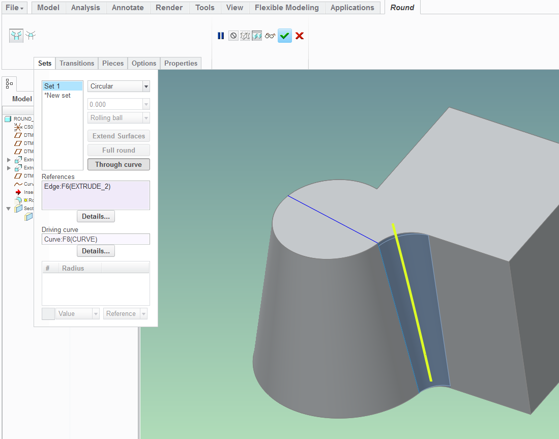
See if you can use the "Thru curve" option for your round:
- Mark as New
- Bookmark
- Subscribe
- Mute
- Subscribe to RSS Feed
- Permalink
- Notify Moderator
Could work. I was looking more for a constant radius, but let me take a look.
Thanks,
Dan
- Mark as New
- Bookmark
- Subscribe
- Mute
- Subscribe to RSS Feed
- Permalink
- Notify Moderator
- Mark as New
- Bookmark
- Subscribe
- Mute
- Subscribe to RSS Feed
- Permalink
- Notify Moderator
Tom,
I really like this approach. We may have a winner! The beauty of this approach is that I am able to do a "blend" feature while creating a mold volume in Creo/Mold.
I could offset the first section with a relations over a given distance to create a nominal draft angle.
I will investigate this further.
Thanks,
Dan
- Mark as New
- Bookmark
- Subscribe
- Mute
- Subscribe to RSS Feed
- Permalink
- Notify Moderator
Tom,
I really thought we (you) were on to something here. I'm not sure if this is an issue yet, but the resulting surface is not a true cylindrical surface. I'm not sure why, but you are unable to add an axis through the resulting "round". Like I said, I'm not sure it's an issue yet.
Thanks,
Dan
- Mark as New
- Bookmark
- Subscribe
- Mute
- Subscribe to RSS Feed
- Permalink
- Notify Moderator
As I mentioned, the only straight line on a cone is one that passes through the vertex. And the only cylindrical fillet that can be tangent to a cone has to be tangent along that straight line, so it cannot also be angled to follow tapered blocks.
My guess it that the blend isn't a true cone, which allows what looks like a cylinder, but is an elliptical section normal to the slope.
Fortunately I already know enough about wire edm. What I don't know is why the design is caught between geometry reality and a machining method that can't produce that geometry. One or the other needs to change.
- Mark as New
- Bookmark
- Subscribe
- Mute
- Subscribe to RSS Feed
- Permalink
- Notify Moderator
This is what you get when you add draft after the fact. What most machinist would want generically.
In this case, you are assured constant draft if both features have the same draft.
Surface tangency is maintained (missing element in sweep methods).
note: transition lines for round-to-cone project to the cone's center. 
- Mark as New
- Bookmark
- Subscribe
- Mute
- Subscribe to RSS Feed
- Permalink
- Notify Moderator
The EDM probe can take on any shape you want if you are using a plunge EDM.
If you are wire EDM'ng this, then you have to decide on what is moving to get the noted draft.
So there is little limitation but if this draft if for molding, typically you would make the straight part and add draft afterward.
Doing this makes for more uniform drafts which are easier to machine (taper bit, single axis and all that).
In this vein, I find it very hard to match drafts with simple resulting rounds since their taper angle is not controllable in the Round feature dialog.
I think you are looking for a "full round" feature for this. You would add your 3rd (intermediate/depth) surface in one of many ways.
- Mark as New
- Bookmark
- Subscribe
- Mute
- Subscribe to RSS Feed
- Permalink
- Notify Moderator
And don't forget boundary blend...
- Mark as New
- Bookmark
- Subscribe
- Mute
- Subscribe to RSS Feed
- Permalink
- Notify Moderator
...and sweep feature in combination of fills and boundary blends merged into a solid.
The challenge with the toolbox we have is to know when the surface is curved from normal.
Features such as Blend and Boundary Blend (top to bottom) is the way the connections are parced.
Even using sweep, you have to be sure to choose constant normal.
Highly configurable
Machinist's nightmare

