
Turn on suggestions
Auto-suggest helps you quickly narrow down your search results by suggesting possible matches as you type.
Showing results for
Please log in to access translation
Turn on suggestions
Auto-suggest helps you quickly narrow down your search results by suggesting possible matches as you type.
Showing results for
Community Tip - New to the community? Learn how to post a question and get help from PTC and industry experts! X
- Community
- Creo+ and Creo Parametric
- 3D Part & Assembly Design
- Re: Large Deformation FEA
Translate the entire conversation x
Please log in to access translation
Options
- Subscribe to RSS Feed
- Mark Topic as New
- Mark Topic as Read
- Float this Topic for Current User
- Bookmark
- Subscribe
- Mute
- Printer Friendly Page
Large Deformation FEA
Oct 27, 2014
11:14 AM
- Mark as New
- Bookmark
- Subscribe
- Mute
- Subscribe to RSS Feed
- Permalink
- Notify Moderator
Please log in to access translation
Oct 27, 2014
11:14 AM
Large Deformation FEA
Hello all:
I've been working on getting FEA going for the small company I work for. I've encountered several challenges so far; I've learned a lot too. I'm finding it too easy to lead myself to believe every change I make is going to be the key to a more accurate simulation.
I'm trying to simulate destructive testing. I'd like to describe what I'm trying at this point and see if anyone has some suggestions on how I could improve. I'll more than welcome any questions, general discussion, or criticism. I'm just trying to learn more.
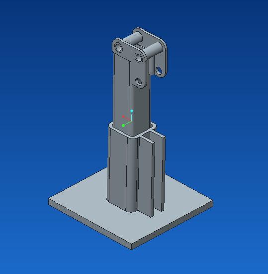
Here is the sample part I'm trying to simulate (2" x 2" x 3/16" tube). It is a weldment and I have bonded contacts on everything verified by the review geometry tool:
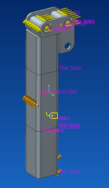
I have fixed displacement on the surfaces (lower bottom and middle, opposite side). I modified the mesh to be thin solid where possible. I also made the middle volume of the tube have smaller elements (0.3 in). I applied a load equal to just half of what I tested to be the max force of 6000 lbf (1500 lbf on each hole).
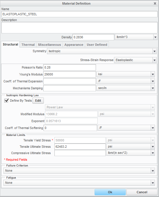
My material definition is below. The only other thing I specify here is the user defined property of the modulus of rigidity (11,600 ksi).
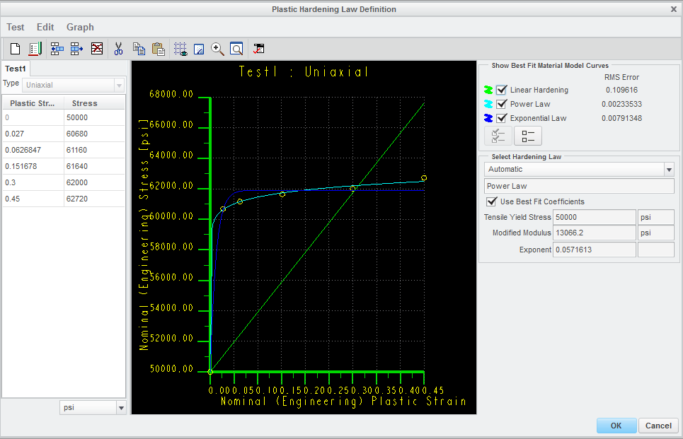
One of my big challenges has been getting a material curve that seems reasonable. I'm sure this could be a discussion on its own. Here is my material hardening curve:
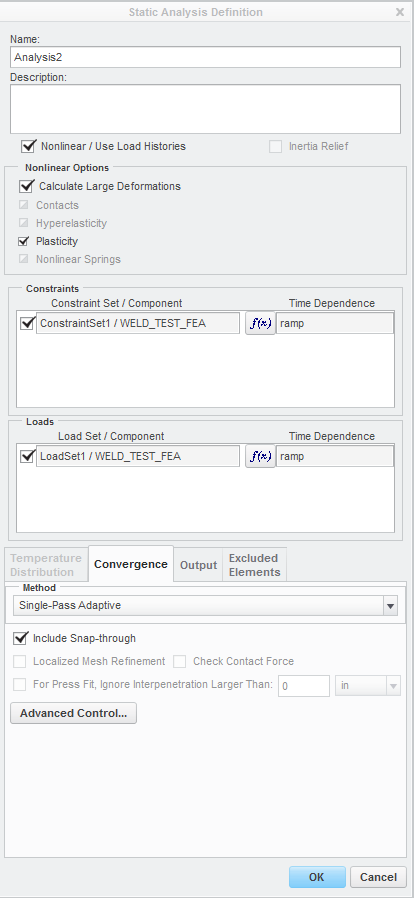
I've been running a staic analysis. I've tried with snap-through and without. I see little to no difference. I've tried running user defined output steps varying from 11-501 with little difference. Here is the analysis I run:
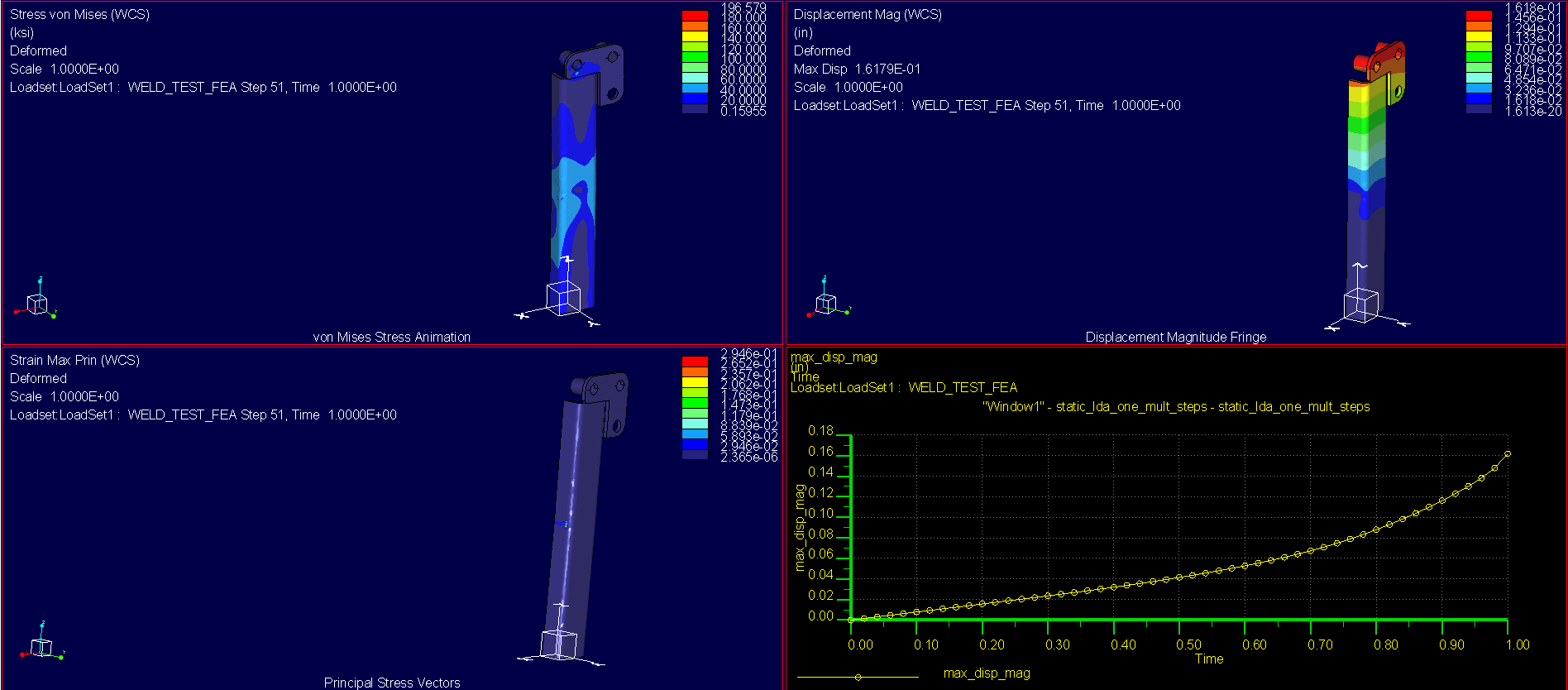
So when I run this, at the previously stated half of max load, the simulation fails at step 32 of 100:
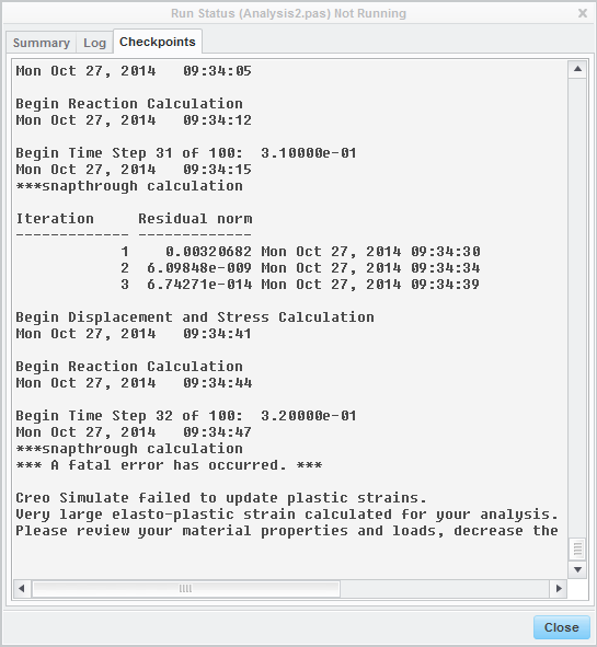
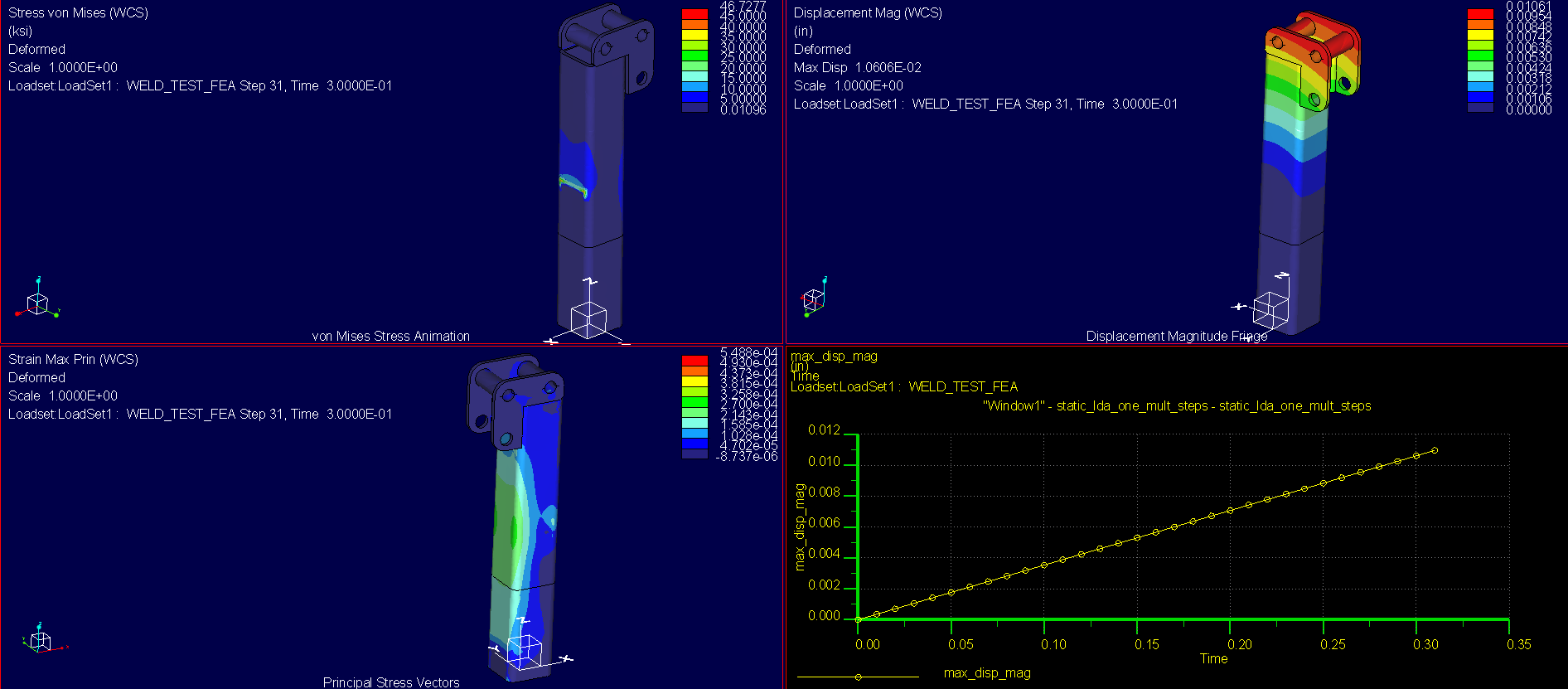
My results show a barely deformed sample with less than plastic deformation stress and very little strain:
If anyone has suggestions or general input about what I'm seeing here, I'd like to hear it!
Thanks for taking the time to look at this!
This thread is inactive and closed by the PTC Community Management Team. If you would like to provide a reply and re-open this thread, please notify the moderator and reference the thread. You may also use "Start a topic" button to ask a new question. Please be sure to include what version of the PTC product you are using so another community member knowledgeable about your version may be able to assist.
Labels:
- Labels:
-
Data Exchange
26 REPLIES 26
Oct 27, 2014
04:20 PM
- Mark as New
- Bookmark
- Subscribe
- Mute
- Subscribe to RSS Feed
- Permalink
- Notify Moderator
Please log in to access translation
Oct 27, 2014
04:20 PM
Can you upload your model? I want to dig-through it first.
Oct 27, 2014
04:31 PM
- Mark as New
- Bookmark
- Subscribe
- Mute
- Subscribe to RSS Feed
- Permalink
- Notify Moderator
Please log in to access translation
Oct 27, 2014
04:31 PM
Thanks for looking Shaun. Let me know if this isn't what you're looking for.
Oct 27, 2014
05:18 PM
- Mark as New
- Bookmark
- Subscribe
- Mute
- Subscribe to RSS Feed
- Permalink
- Notify Moderator
Please log in to access translation
Oct 27, 2014
05:18 PM
Are components 711959800. Hinge_weld, and Hinge_Joint all welded together? Does that applied load always act along the x-direction, even as the tube deforms?
Oct 27, 2014
05:23 PM
- Mark as New
- Bookmark
- Subscribe
- Mute
- Subscribe to RSS Feed
- Permalink
- Notify Moderator
Please log in to access translation
Oct 27, 2014
05:23 PM
The two Hinge_Joint parts are welded to the two 711959800 parts. My part Hinge_Weld is literally the weld that I made as a part. The offset makes that part of the weldment free without some contacting geometry.
Oct 27, 2014
06:04 PM
- Mark as New
- Bookmark
- Subscribe
- Mute
- Subscribe to RSS Feed
- Permalink
- Notify Moderator
Please log in to access translation
Oct 27, 2014
06:04 PM
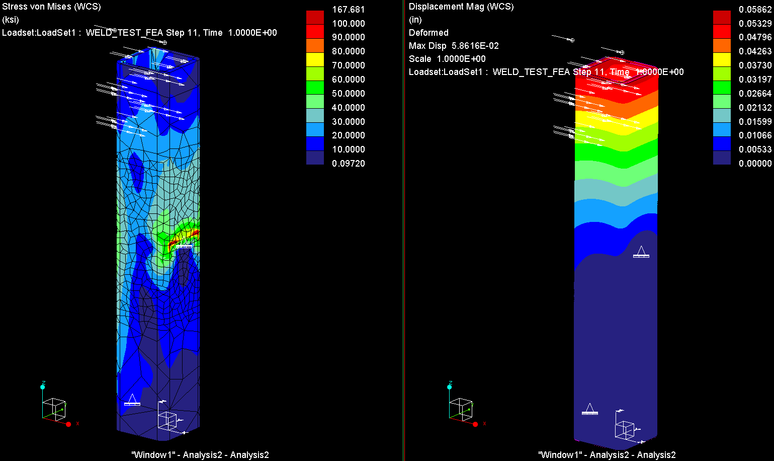
I'll need to do some more testing when I get time, but my initial thought is that the issue is due to sharp change in the tangential stiffness of your material when it goes into the plastic region. This is typically handled via the snap-through effect, but there currently is an (apparent) bug with the span-through effect in Creo 2.0 and 3.0. I changed your elastoplastic material properties to linear-hardening with a tangent modulus that is 10% of your Young's Modulus and it solved:
Also, you're using fixed-constraints (i.e. the surface cannot move at all); is this realistic? How was the physical test set up? Were supports welded to the tube in these locations?
Oct 28, 2014
09:33 AM
- Mark as New
- Bookmark
- Subscribe
- Mute
- Subscribe to RSS Feed
- Permalink
- Notify Moderator
Please log in to access translation
Oct 28, 2014
09:33 AM
Thanks Shaun.
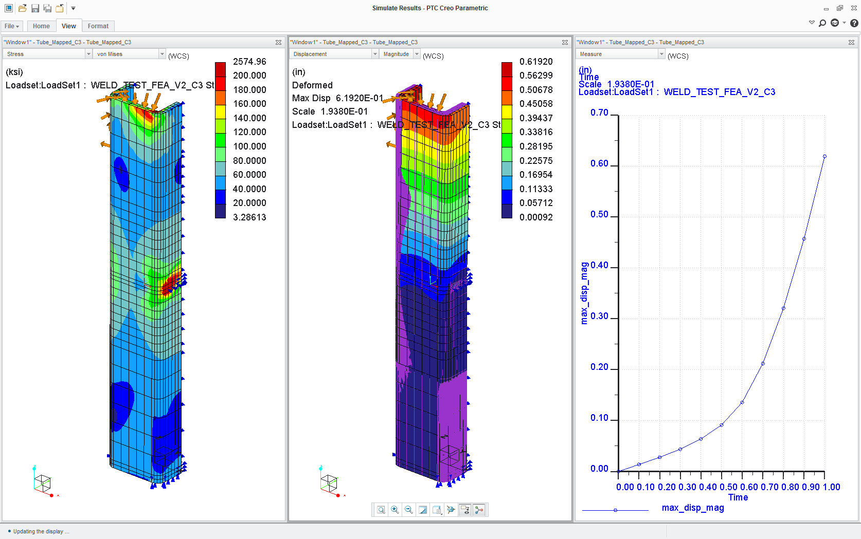
I went ahead and ran the linear hardening as you specified. I did the same load positioning as I had before, but I used two 3000 lbf loads to get more deformation as I saw in the real tests. Here's what I got, similar to yours:
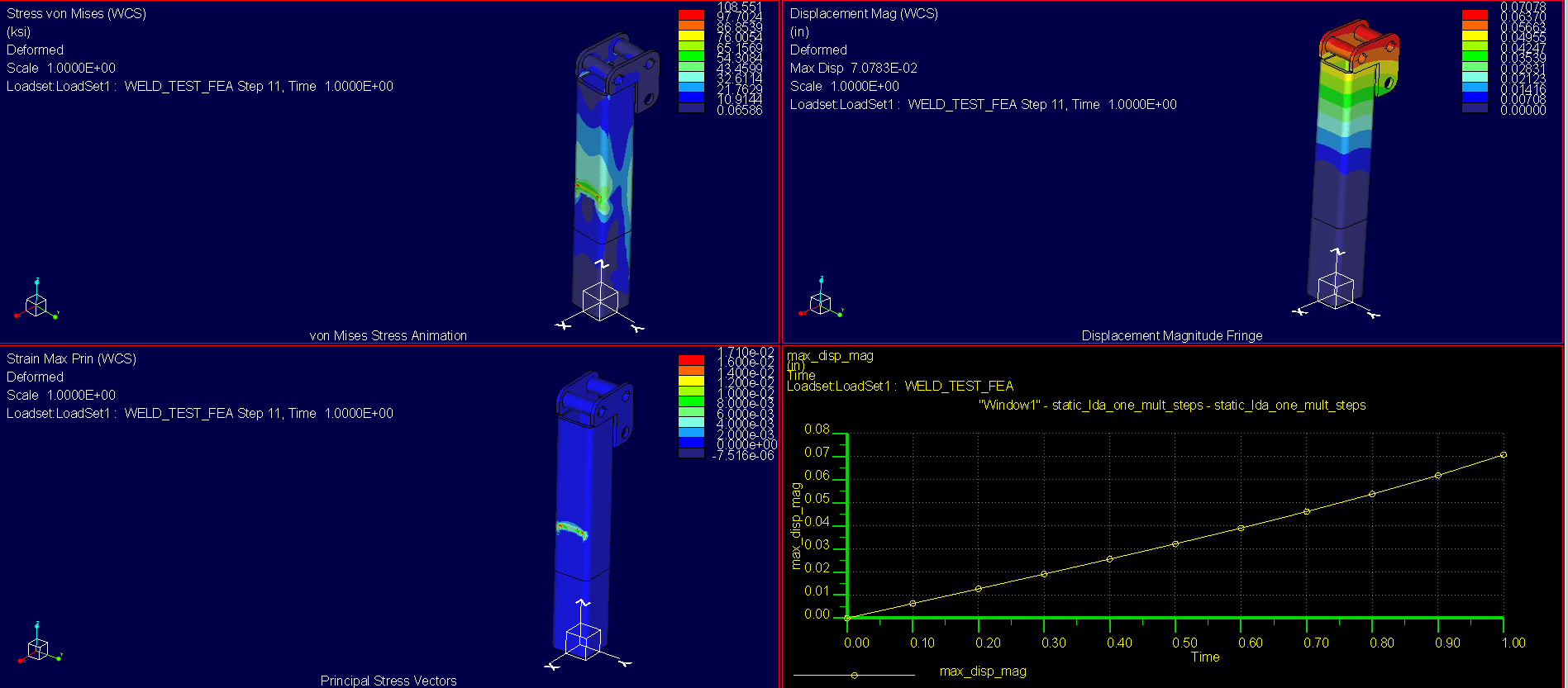
That just doesn't make sense to me. Linear hardening should give more plastic deformation than my original material curve, right? And why do we have these off-the-charts stresses with very little strain?
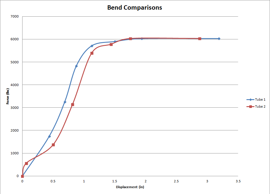
Here is some real data I collected for the tube to show you what I'm shooting for:
I was going to run a contact analysis, but quickly figured out that won't work for nonlinear simulation in Creo 2.0. I just drop the sample into this larger tube that is reinforced. Here is a model of the test stand (It is suppressed in the assembly I uploaded):
Thanks,
Chris
Oct 28, 2014
03:55 AM
- Mark as New
- Bookmark
- Subscribe
- Mute
- Subscribe to RSS Feed
- Permalink
- Notify Moderator
Please log in to access translation
Oct 28, 2014
03:55 AM
Chris,
I have not looked at your model, but I'd like to share some of my experiences:
- Singularities such as reentrant corners will make it difficult to for an elasto-plastic analysis to converge. If you expect plastic deformation in a portion of the model but you have singularities elsewhere, create a volume region where you want to analyze yield and use elasto-plastic properties only for that region. Make sure that the volume region is large enough so that the stress levels at the region's boundaries are below yield. Use linear material properties elsewhere. If you have singularities, it is a good idea to use a AutoGEM control on a volume region to exclude those elements from convergence, otherwise the solver will waste time on increasing P-level at those singularities.
- Note that the material properties you enter, for the elasto-plastic material only account for the plastic strain, not the elastic strain. This mean that if the yield stress is 250 MPa, then the first point of the curve that you enter should be (0,250). I.e. zero plastic strain at 250 MPa. Additional points should only account for the increase in plastic strain vs. true stress.
- Solving non-linear problems, for example elasto-plastic analyses is more sensitive to the mesh. If it is possible, try to use "Mapped mesh", "Prismatic elements" etc.
Oct 28, 2014
08:37 AM
- Mark as New
- Bookmark
- Subscribe
- Mute
- Subscribe to RSS Feed
- Permalink
- Notify Moderator
Please log in to access translation
Oct 28, 2014
08:37 AM
Thanks for the info Mats.
- That's a good idea to use a volume region and separate it as an elastoplastic material. However, this is just a very small sample that I'm trying to use for calibration of simulation. I feel that once I get into much more complex structures that creating these volume regions would get into too much guesswork. You have said a lot about singularities. Do you refer to singularities just as sharp corners?
- I understand the plastic curve, but in reference to true stress, why is there no function allowing stress to hit a vertical tangent? As in, after I hit about 20% elongation, I would prefer to see a high stress region that I would understand to be the point of failure. I'm not sure if I'm looking at that right.
Thanks,
Chris
Oct 28, 2014
10:09 AM
- Mark as New
- Bookmark
- Subscribe
- Mute
- Subscribe to RSS Feed
- Permalink
- Notify Moderator
Please log in to access translation
Oct 28, 2014
10:09 AM
Chris,
Any singularity in the solid with non-linear material property, that result in a stress that does not converge is problematic. I see now that your model has a few singularities like that.
Around the top of the structure, around the welds etc. there are a few reentrant corners. Typically I would create rounds to remove those singularities. Or, and this is what I did, create a volume region of this portion of the structure, and assign linear material properties to this region. Also create an "Isolate for exclusion" AutoGEM control, for this volume region, so that the solver won't waste time to increase P-level where you have singluarities...
Other singularities are the constraints who prevent tangential displacement. This means that there is an abrupt change in stiffness between the perfectly rigid constraint and the elasto-plastic steel. Is this realistic? In my model I have released tangential displacement, so as to mimic a contact.
As Shaun mentioned above, your material property, with a significant drop in tangential stiffness looks suspicious. I changed the property as Shaun did. The stress-strain functions available (linear hardening, power law, exponential law) do not allow the stress-strain curve to become vertical I guess because that is not realistic. The tangential stiffness (true stress, true strain) is typically finite, and if anything, it becomes lower as the point of failure is approached. As is the case with exponential and power law hardening.
I used symmetry to reduce the number of elements. The geometry, loads and constraints are symmetric, right?
I removed your "thin solid" AutoGEM control; I got some meshing problems. It could be because I added another volume region. Initially, I'm not interested in accuracy, I just want the analysis to run without error.
The model that I have uploaded seems to be able to run the analysis through, it's in load step 15 of 51, pass 2. I need to get back to work... I hope this helps.
/Mats L/Avalon Innovation/
Oct 28, 2014
05:38 PM
- Mark as New
- Bookmark
- Subscribe
- Mute
- Subscribe to RSS Feed
- Permalink
- Notify Moderator
Please log in to access translation
Oct 28, 2014
05:38 PM
Mats:
I finally got your run to complete after 7 hours. I like your methods very much.
I had never experimented with the excluded elements. I think that will be a very useful function for me. I'll start tomorrow continuing with your model to see if I can adjust the material to get reasonable results. I'm open to suggestions for this as well.
As far as run time... This took much longer to run than expected. I have a 3.7 GHz, 16 GB RAM desktop and I have the SOLRAM set to 8000 MB. Anything else I need to look at that may be able to increase speed?
Thanks,
Chris
Oct 28, 2014
05:55 PM
- Mark as New
- Bookmark
- Subscribe
- Mute
- Subscribe to RSS Feed
- Permalink
- Notify Moderator
Please log in to access translation
Oct 28, 2014
05:55 PM
You'll notice that the model I ran did not have your weldment feature at the top of the tube; I used a Total Load At Point (TLAP) to approximate the load transfer through the weldment. I think that, for now, it'd be worth it for you to do this to simplify your model while you work on getting a mesh and model setup for approximating the contact between the tube and the large tube. This will help reduce your element count, thereby decreasing the run-time (even more so if you didn't restrict the p-order on your excluded elements).
You'll find out rather quickly the non-linear analyses take substantially more time to run that linear problems, and that there is a lot of trail-and-error associated with creating a numerically stable and accurate study (hence my suggestion to remove the top weldment components).
Oct 29, 2014
08:43 AM
- Mark as New
- Bookmark
- Subscribe
- Mute
- Subscribe to RSS Feed
- Permalink
- Notify Moderator
Please log in to access translation
Oct 29, 2014
08:43 AM
I had never used the TLAP. I assume the main use for it would be once parts are excluded? Good to know. Also, you talk about restricting the P-Order... I've never messed with that much, is it essentially like running a quick check that limits the polonomial order to 3?
Oct 28, 2014
06:41 PM
- Mark as New
- Bookmark
- Subscribe
- Mute
- Subscribe to RSS Feed
- Permalink
- Notify Moderator
Please log in to access translation
Oct 28, 2014
06:41 PM
So here's a quick revised model. I've elimated the top weldment, used a mapped mesh, used the linear-hardening elastoplastic material model, and adjusted the constraints; the whole model took a little under 21 mintues to solve (and based on this initial set of results, I think a corase mesh is do-able). Of course, there is still more work that needs to be done, but we're on the right track.
Oct 29, 2014
08:47 AM
- Mark as New
- Bookmark
- Subscribe
- Mute
- Subscribe to RSS Feed
- Permalink
- Notify Moderator
Please log in to access translation
Oct 29, 2014
08:47 AM
Well done, Shaun.
After just this discussion, I am quickly realizing that I've merely been walking around the rim of FEA and you all dove in long ago haha.
What's going on with all those arrows pointing every direction at the top?
Thanks again,
Chris
Oct 29, 2014
02:25 PM
- Mark as New
- Bookmark
- Subscribe
- Mute
- Subscribe to RSS Feed
- Permalink
- Notify Moderator
Please log in to access translation
Oct 29, 2014
02:25 PM
Those arrows are from the two 3 kip loads, and they're pointing every-which-way because they are applied using a TLAP. You can read about TLAPs and Weighted-Links in the help section, but basically they're a method of load transfer that doesn't add stiffness to the model. PTC changes the visual representation of TLAPs in Creo 3.0.
Oct 29, 2014
04:43 AM
- Mark as New
- Bookmark
- Subscribe
- Mute
- Subscribe to RSS Feed
- Permalink
- Notify Moderator
Please log in to access translation
Oct 29, 2014
04:43 AM
As far as run time... This took much longer to run than expected. I have a 3.7 GHz, 16 GB RAM desktop and I have the SOLRAM set to 8000 MB. Anything else I need to look at that may be able to increase speed?
Hi Chris,
- What exact CPU do you have? (Hold Windows key and press Pause/Break to get your system properties window up.)
- What were the total elapsed, and total CPU times reported at the end of the run summary (.rpt file)?
- Where are you putting the temporary and results files - network drive, local spinning hard disk, local SSD or RAM drive? Those are in order from slowest to fastest.

Oct 29, 2014
08:39 AM
- Mark as New
- Bookmark
- Subscribe
- Mute
- Subscribe to RSS Feed
- Permalink
- Notify Moderator
Please log in to access translation
Oct 29, 2014
08:39 AM
Thanks for looking into this Jonathan.
Here's my CPU:

Here's the run summary:
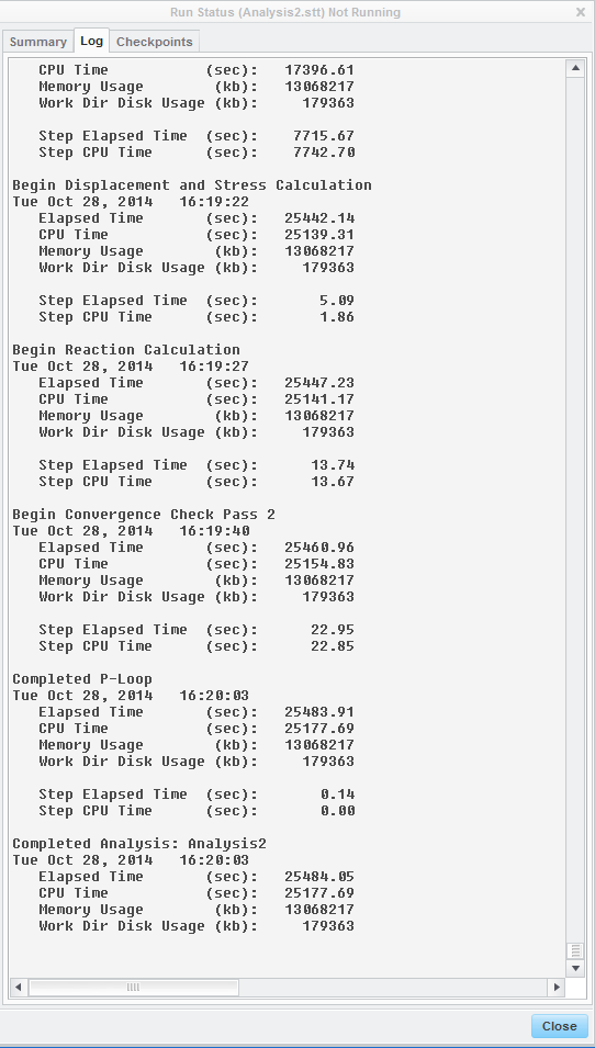
And I was working on my (C:) drive... Would that be a local hard disk or RAM drive? I don't have anything SSD around here.
Any recommendations would be greatly appreciated!
Thanks,
Chris
Oct 29, 2014
09:22 AM
- Mark as New
- Bookmark
- Subscribe
- Mute
- Subscribe to RSS Feed
- Permalink
- Notify Moderator
Please log in to access translation
Oct 29, 2014
09:22 AM
Well, the CPU is pretty capable and C: (local hard drive) is a reasonable place to put the temp files. It's clearly working mostly on just one core, but I think that's standard for Large Deformation.
13 GB total memory use is reported... one wild last guess: did you have anything else large taking up system memory, maybe a (really) big assembly or some other software using a chunk of RAM? Otherwise I can't see any obvious reasons for the long solve time, especially compared to Mats' laptop.
Oct 29, 2014
09:31 AM
- Mark as New
- Bookmark
- Subscribe
- Mute
- Subscribe to RSS Feed
- Permalink
- Notify Moderator
Please log in to access translation
Oct 29, 2014
09:31 AM
Well I was working on another large assembly (232,960 KB). But I was working on it on the network drive. Not sure if that makes a difference or not. It was just running on the backburner I guess...
Thanks,
Chris
Oct 28, 2014
05:52 PM
- Mark as New
- Bookmark
- Subscribe
- Mute
- Subscribe to RSS Feed
- Permalink
- Notify Moderator
Please log in to access translation
Oct 28, 2014
05:52 PM
Mat's has some excellent points here.
Oct 29, 2014
03:36 AM
- Mark as New
- Bookmark
- Subscribe
- Mute
- Subscribe to RSS Feed
- Permalink
- Notify Moderator
Please log in to access translation
Oct 29, 2014
03:36 AM
Chris,
On my laptop, 64 bit, 2x2.7 GHz, 16 GB RAM, it took just under 2 hours... peculiar that it took longer on your desktop. Is it a 32-bit computer? In my run, it was the last few load steps that were time consuming.
Using a mapped mesh as Shaun did will obviously make the analysis run faster. Also replacing the constraint with a contact region and including at least a portion of the "tube" where it touches the beam might make it run more smoothly aswell. It might be counter-intuitive that introducing another non-linear phenomenon actually makes the analysis run faster. But when analyzing non-linear effects, such as plasticity, anything that is unnaturally stiff, such as a rigid constraint, makes it more difficult for the non-linear solver to converge, i.e. to find the deformed state, stresses and reaction forces that are in equilibrium. An elastic contact is more realistic, or more "natural" than the rigid constraint, so there is a chance that introducing a contact region might make it easier for the non-linear solver to converge.
Here is a simulation I did for a press brake forming operation, two contacts, plastic deformation in the sheet steel. It's plane strain (2D) but for some reason I made it in 3D. It should be possible to to this in 2D aswell...
(There seems to be an issue uploading my video file... will try to resolve it)
Oct 29, 2014
09:24 AM
- Mark as New
- Bookmark
- Subscribe
- Mute
- Subscribe to RSS Feed
- Permalink
- Notify Moderator
Please log in to access translation
Oct 29, 2014
09:24 AM
When I first tried to do this simulation, I tried to include the test stand with contact interfaces. It came up with an error... Something about contacts not allowed in nonlinear materials. Although upon a second try it seems it will run it. It must be another tedious application that I'll have to become more familiar with.
Do you ever recommend a fixed displacement? Say I got down to the plate on the test stand... Would that be safe to fix in all directions? I understand it's going to take experience to really get a feel for it.
Thanks again,
Chris
Oct 29, 2014
09:51 AM
- Mark as New
- Bookmark
- Subscribe
- Mute
- Subscribe to RSS Feed
- Permalink
- Notify Moderator
Please log in to access translation
Oct 29, 2014
09:51 AM
P.S. Awesome press brake model. I notice everything you all are showing me is as simple as possible. Is it reasonable to try to analyze a frame assembly all at once, or is it recommended to take it apart and run a segment at a time?
Oct 29, 2014
02:38 PM
- Mark as New
- Bookmark
- Subscribe
- Mute
- Subscribe to RSS Feed
- Permalink
- Notify Moderator
Please log in to access translation
Oct 29, 2014
02:38 PM
"Also replacing the constraint with a contact region and including at least a portion of the "tube" where it touches the beam might make it run more smoothly aswell. "
I think replacing the rigid constraints with something elastic is the next step. That being said, the restrictions on mapped meshing and contact are extremly limited, so my guess is that any contact model will force Chris to use a tet mesh (for whatever reason, a prismatic mesh control causes contact interfaces to fail).
My thought was that it might be worth trying to mimic the contact regions with springs and weighted-links, but I think a little testing would need to be done first. If I recall correctly, only simple springs can be used in non-linear analyses, and using weighted-links can lead to error in the results (at least in certain cases).
"Here is a simulation I did for a press brake forming operation, two contacts, plastic deformation in the sheet steel. It's plane strain (2D) but for some reason I made it in 3D. It should be possible to to this in 2D aswell..."
Did PTC finally add large-displacement/strain formulation into any of the 2D idealizations?
Nov 03, 2014
08:27 AM
- Mark as New
- Bookmark
- Subscribe
- Mute
- Subscribe to RSS Feed
- Permalink
- Notify Moderator
Please log in to access translation
Nov 03, 2014
08:27 AM
Shaun, I can't remember why I didn't run this as a 2D analysis, but lack of functionality might have been the reason. It's been a couple of years since I did it. If the problem is 2D it is sufficient to use a thin, typically 1 element thick slice of the structure, which is "almost 2D"./Mats
Oct 29, 2014
05:11 PM
- Mark as New
- Bookmark
- Subscribe
- Mute
- Subscribe to RSS Feed
- Permalink
- Notify Moderator
Please log in to access translation
Oct 29, 2014
05:11 PM
Shaun, Mats, Jonathan:
Thank you all very much for the insight! I have a lot more to experiment with now. This discussion has been very useful and I hope others benefit from it as well.
-Chris


