Community Tip - Visit the PTCooler (the community lounge) to get to know your fellow community members and check out some of Dale's Friday Humor posts! X
- Community
- Creo+ and Creo Parametric
- 3D Part & Assembly Design
- Mechanism analysis
- Subscribe to RSS Feed
- Mark Topic as New
- Mark Topic as Read
- Float this Topic for Current User
- Bookmark
- Subscribe
- Mute
- Printer Friendly Page
Mechanism analysis
- Mark as New
- Bookmark
- Subscribe
- Mute
- Subscribe to RSS Feed
- Permalink
- Notify Moderator
Mechanism analysis
Hi All,
I have a problem, where I want to analyse how slider block can affect the guide bar. I have looked through good few tutorials on YouTube but nothing seems to match.
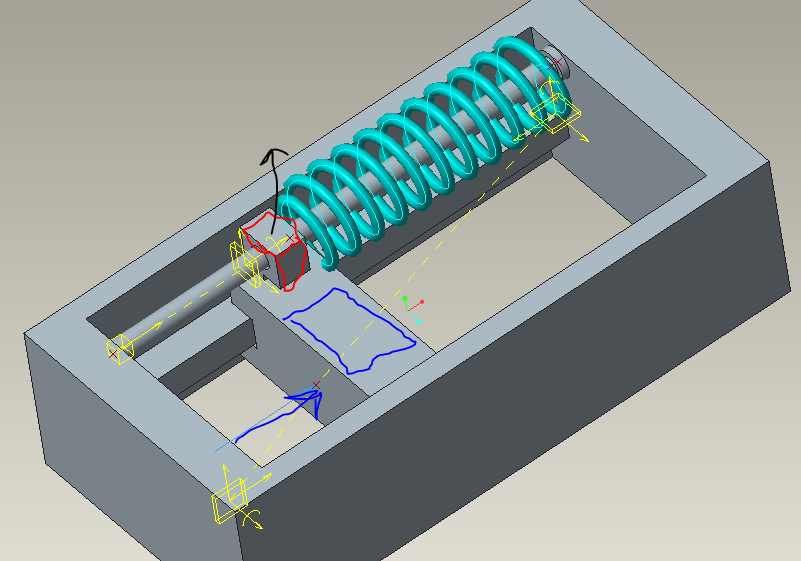
There is a welded frame where a slide(marked blue) is moved by hydraulic cylinder within prescribed range. In case of cylinder failure the spring through slider block marked in red would keep the slide in required position.
I have a problem constraining the sliding block. I have tried applying coincident constrains to block walls and slide slot walls, also constrain the axis on bar and slide. But not sure if that replicates the reality where (noticed from real life application) due to repeated operation the block moves out of position (black arrow) and bends the bar. I think would need to constrain it in a way that there would be a contact defined between the bar and the block, as a result I might be able to see the travel of sliding block I y direction and deflection if any on the bar.

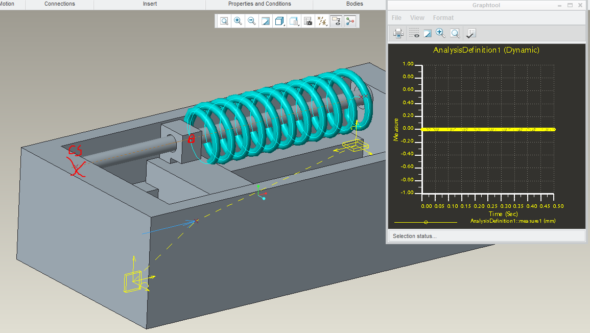
I have ran the analysis and it shows the point did not moved at all in y direction.

Creo mechanism analysis is a new tool for me, not sure if this type of analysis is available at all, so any help is much appreciated ![]()
have attached the assembly files (all values are random)
This thread is inactive and closed by the PTC Community Management Team. If you would like to provide a reply and re-open this thread, please notify the moderator and reference the thread. You may also use "Start a topic" button to ask a new question. Please be sure to include what version of the PTC product you are using so another community member knowledgeable about your version may be able to assist.
- Mark as New
- Bookmark
- Subscribe
- Mute
- Subscribe to RSS Feed
- Permalink
- Notify Moderator
I do not open RAR files but your challenge is fairly straight forward.
You can use a pin constraint with the optional relations defined.
you can also use a slider constraint.
Remember that you can add multiple mechanism constraints to a single function.
If you are using core-Creo without the dynamics extension, you can create a servo motor relation to a linear element by using gear links.
- Mark as New
- Bookmark
- Subscribe
- Mute
- Subscribe to RSS Feed
- Permalink
- Notify Moderator
Antonius Dirriwachter ha scritto:
If you are using core-Creo without the dynamics extension, you can create a servo motor relation to a linear element by using gear links.
Hi Antonius,
could you explain better this last thing?
Thanks
- Mark as New
- Bookmark
- Subscribe
- Mute
- Subscribe to RSS Feed
- Permalink
- Notify Moderator
You can create a generic gear connection between linear to linear, rotational to linear, or rotational to rotational.
Where you would assign a servo motor to the little axis/rotate icon, you can pick this for gear connection too. If the constraint is "cylinder" for instance, it is a linear motion. So you can link the rotational axis to a linear axis and the dialog will let you tell it that you want "X" amount of travel for every "Y" amount of rotation... And visa-versa ![]() This is mostly to maintain relations between moving elements. If you assign a servo motor, the elements remain linked.
This is mostly to maintain relations between moving elements. If you assign a servo motor, the elements remain linked.
- Mark as New
- Bookmark
- Subscribe
- Mute
- Subscribe to RSS Feed
- Permalink
- Notify Moderator
Sorry but...can I relate the motion law of a servo motor to a displacement of another constrain?
Sorry but at the moment I can't access to my workstation to verify...but the manners that you have to setting the motion law in the servo are, referred to displacement, velocity and acceleration: constant, ramp, cycloid, sine, and USER DEFINED.
I have used this last one only with the importation of external datas.
Do you mean that you could assign here a relation directly with another constrain?
- Mark as New
- Bookmark
- Subscribe
- Mute
- Subscribe to RSS Feed
- Permalink
- Notify Moderator
You can use the mechanism constraints to connect mechanism elements, yes.
I doubt you can access the servo data directly.
What I have done in the past is create a "hidden" rotational servo component, and created a user defined gear connection to a linear element.
Here is a sample that uses the lead-screw to initiate motion of the moving element mimicking the thread pitch.
- Mark as New
- Bookmark
- Subscribe
- Mute
- Subscribe to RSS Feed
- Permalink
- Notify Moderator
Hi,
unfortunately at the moment I can't download the rar file to check your assembly but I can give you some suggestion:
you you need more than a simple analysis of position, you must link the bodies in manner that the degrees of freddom of each one are reduced to zero.
To correctly understand if you have acted well, there are two measures within the Mechanism/Motion environment called: "degrees of freedom" and "redundancies".
The first one reports the dof that are not yet constrained.
The second one reports if you have constrained more than one time the same body. Eg: a shaft that rotates on his own axis must have only 1 dof; if you put on it a pin you constrain it with 5 degrees of constraint and, with a motor, you have all the dof settled. But if you put on the shaft 2 pins, thinked that in the reality you have two bearings, than you will have 5x2=10 doc + 1 doc due to the motor.
So the previous measures return: dof=0 and redundancied=5.
Remember that the application of a servo motor to a constrain means that you remove, from that constrain, one dof. Eg: a pin have 5 degrees of constrain and only 1 of freedom; if you apply on a pin a servo motor you remove the freedom on then axis of motion because you impose a law of motion.
Bye


