
Turn on suggestions
Auto-suggest helps you quickly narrow down your search results by suggesting possible matches as you type.
Showing results for
Please log in to access translation
Turn on suggestions
Auto-suggest helps you quickly narrow down your search results by suggesting possible matches as you type.
Showing results for
Community Tip - Have a PTC product question you need answered fast? Chances are someone has asked it before. Learn about the community search. X
- Community
- Creo+ and Creo Parametric
- 3D Part & Assembly Design
- Re: Minor but annoying - easy improvements?
Translate the entire conversation x
Please log in to access translation
Options
- Subscribe to RSS Feed
- Mark Topic as New
- Mark Topic as Read
- Float this Topic for Current User
- Bookmark
- Subscribe
- Mute
- Printer Friendly Page
Minor but annoying - easy improvements?
Jan 16, 2012
12:18 PM
- Mark as New
- Bookmark
- Subscribe
- Mute
- Subscribe to RSS Feed
- Permalink
- Notify Moderator
Please log in to access translation
Jan 16, 2012
12:18 PM
Minor but annoying - easy improvements?
Following another thread about real-world use versus PTC trainers' knowledge, how about we start a list of small things, which ought to be relatively easy for PTC to change, that nonetheless annoy you on a day-to-day basis (and always seem to be passed over in favour of introducing dashboards and ribbons)?
Since various PTC people contribute here, if we keep it tidy and concise perhaps some of our issues could be considered for addressing in imminent versions of Pro/E / Creo (/wishful thinking...)
So, here are some starters:
- Angle x D chamfers almost always choose the wrong direction for the angle by default
- Surface merges almost always choose the wrong sides of the quilts to keep by default
- Save a Copy leaves you editing the original model (opposite to Windows Save As), whilst Backup leaves you editing the backup model (why would you make a backup and then change the backup?)
- When you're working in "widget.prt" and you create a new drawing, Pro/E assumes the name "drw0001". How likely is it that you don't want to create "widget.drw" at this point?
This thread is inactive and closed by the PTC Community Management Team. If you would like to provide a reply and re-open this thread, please notify the moderator and reference the thread. You may also use "Start a topic" button to ask a new question. Please be sure to include what version of the PTC product you are using so another community member knowledgeable about your version may be able to assist.
Labels:
- Labels:
-
General
121 REPLIES 121
Feb 25, 2012
11:41 AM
- Mark as New
- Bookmark
- Subscribe
- Mute
- Subscribe to RSS Feed
- Permalink
- Notify Moderator
Please log in to access translation
Feb 25, 2012
11:41 AM
The ability to export a sketch as a DWG (or DXF) directly. Having to go through the drawing module is a needless waste of time.
Feb 27, 2012
09:47 AM
- Mark as New
- Bookmark
- Subscribe
- Mute
- Subscribe to RSS Feed
- Permalink
- Notify Moderator
Please log in to access translation
Feb 27, 2012
09:47 AM
The ability to replacee entities in sketcher much easier, one after another.
Feb 28, 2012
06:27 PM
- Mark as New
- Bookmark
- Subscribe
- Mute
- Subscribe to RSS Feed
- Permalink
- Notify Moderator
Please log in to access translation
Feb 28, 2012
06:27 PM
Sweep Section orientation is in the opposite direction as regular sketch creation. Regular sketch is oriented so arrow is pointing away from you. When the section is created for a Sweep feature the arrow is pointing towards you (opposite to what is intuitive).
Mar 01, 2012
02:19 PM
- Mark as New
- Bookmark
- Subscribe
- Mute
- Subscribe to RSS Feed
- Permalink
- Notify Moderator
Please log in to access translation
Mar 01, 2012
02:19 PM
Why on earth should i select a particular tab in the ribbon first to be able to modify an entity on a drawing?
This adds to the amount of clicks you should do when working on the drawing... and holding "Ctrl" while you select an entity (view, dimensions, table etc.) does not help because it allows you only to select the entity, but does not allow you to change it until you select the particular tab in the ribbon.
I get the feeling that PTC is going completely backwards on this one: instead of automatically selecting the appropriate tab in the ribbon (like in MS Word) when you select an entity, they ask you to select the appropriate tab first so you can work with the particular entity.
This is very counterproductive and frustrating!
Mar 01, 2012
02:31 PM
- Mark as New
- Bookmark
- Subscribe
- Mute
- Subscribe to RSS Feed
- Permalink
- Notify Moderator
Please log in to access translation
Mar 01, 2012
02:31 PM
In the following thread, see post number 85 on page 7.
http://communities.ptc.com/thread/32436?start=75&tstart=0
They did go a bit backwards, then they fixed it. If only they would have fixed it in a datecode for Creo Elements/Pro 5.0.
Mar 02, 2012
08:01 AM
- Mark as New
- Bookmark
- Subscribe
- Mute
- Subscribe to RSS Feed
- Permalink
- Notify Moderator
Please log in to access translation
Mar 02, 2012
08:01 AM
Previews, like in the Expand feature, should not happen until after I have entered a value. There's no need to generate previews of Pro/E's assumptions that obviously won't work. It won't even let you stop the calculations until after it's finished it's own preview.
Mar 05, 2012
06:01 AM
- Mark as New
- Bookmark
- Subscribe
- Mute
- Subscribe to RSS Feed
- Permalink
- Notify Moderator
Please log in to access translation
Mar 05, 2012
06:01 AM
When using Creo 1.0 and editing a feature, add to right mouse click "OK" & "Cancel" the same as when editing a sketch.
This would be very useful when the ribbon is minimized for you would not have to expand the ribbon to confirm the command.
Mar 08, 2012
04:16 PM
- Mark as New
- Bookmark
- Subscribe
- Mute
- Subscribe to RSS Feed
- Permalink
- Notify Moderator
Please log in to access translation
Mar 08, 2012
04:16 PM
One of the biggest issues I have is with the mirrored features and not being allowed to add or change references. This is a big time waster deleting mirrored features and fixing all the downstream geometry.
How about having the ability to toggle colors of a part or even directly have multiple colored parts of the same geometry. There are numerous places this would be benificial.
How about a config option to locate the Sketch set-up dialog box on the left side of the screen where all the other commands/dash boards are?
If there is going to be action/object and object/action ways to model, then provide ways to do ALL features like this.It is very annoying and misleading to have greyed out commands just because you have not selected the appropriate geometry first.
Probably not a minor change, but will Pro/E (Creo) ever be able to shell and give you the option to create square corners when the radius is smaller and the wall thickness. This also applies to the small surfaces that limit shelling.
Mar 08, 2012
06:20 PM
- Mark as New
- Bookmark
- Subscribe
- Mute
- Subscribe to RSS Feed
- Permalink
- Notify Moderator
Please log in to access translation
Mar 08, 2012
06:20 PM
Select "window" in dwg mode for "using edges".
Mar 12, 2012
01:15 PM
- Mark as New
- Bookmark
- Subscribe
- Mute
- Subscribe to RSS Feed
- Permalink
- Notify Moderator
Please log in to access translation
Mar 12, 2012
01:15 PM
Confim, not cancel, repeat component placement with middle mouse button.
Mar 12, 2012
01:50 PM
- Mark as New
- Bookmark
- Subscribe
- Mute
- Subscribe to RSS Feed
- Permalink
- Notify Moderator
Please log in to access translation
Mar 12, 2012
01:50 PM
In assembly mode when you are adding a constraints...that box is locked in place and covers up constraints Iwant to select...GRRRRRR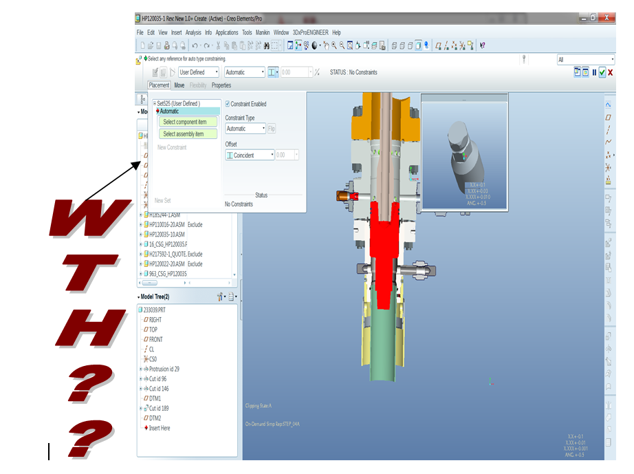
Mar 19, 2012
12:19 PM
- Mark as New
- Bookmark
- Subscribe
- Mute
- Subscribe to RSS Feed
- Permalink
- Notify Moderator
Please log in to access translation
Mar 19, 2012
12:19 PM
When renaming an assembly family table the first part of all instance names (the parent part name or number) should rename automatically. I can't think of many cases where these would be associated to the previous part number instead of the new one.
Mar 26, 2012
09:58 AM
- Mark as New
- Bookmark
- Subscribe
- Mute
- Subscribe to RSS Feed
- Permalink
- Notify Moderator
Please log in to access translation
Mar 26, 2012
09:58 AM
- Adjust the behaviour of View -> Display Settings -> Visibilities (the closest thing we have to a dynamic cross-section) so that the actual model extents are close to 0% and 100%. At the moment, a typical model doesn't start to be clipped until 40-45%, and extends only to 55-60%, which means that each 1% increment is a large step in model depth, and it's difficult to close in on particular details. This is a very useful tool - we have it on a mapkey - but it could be just that bit better.
- Add a proper dynamic cross-section, parallel to any plane rather than just the screen...
Mar 26, 2012
10:01 AM
- Mark as New
- Bookmark
- Subscribe
- Mute
- Subscribe to RSS Feed
- Permalink
- Notify Moderator
Please log in to access translation
Mar 26, 2012
10:01 AM
The drawing MIL SPEC specifies 2 differnt size texts for Draing notes and text in the tables. PTC only has 1 config for default text size so either: You always have to change the charachteristic of your font in the each box of the table OR you have to always change the size of the notes on the drawing. If you had 2 configs for text attributes you couold eliminate all of thus combersone work.
Mar 26, 2012
10:13 AM
- Mark as New
- Bookmark
- Subscribe
- Mute
- Subscribe to RSS Feed
- Permalink
- Notify Moderator
Please log in to access translation
Mar 26, 2012
10:13 AM
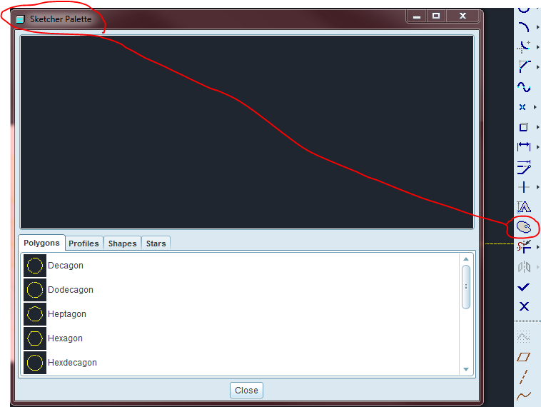
Suggestion - add commonly used shapes to sketcher. examples - round ended slots with the origin at centre, hex shape, keyhole shape (round slot with larger hole at one end), rib shape (narrow rectangle with angled sides, with pre-defined angle dimensions on sides), drilled hole sketch for rotated cuts (rectangle with 59 deg angled bottom edge), T shaped sketch for T slots, triangle sketches, one sharp one with radisued corners.
Thanks Jeff Dayman
Mar 26, 2012
11:18 AM
- Mark as New
- Bookmark
- Subscribe
- Mute
- Subscribe to RSS Feed
- Permalink
- Notify Moderator
Please log in to access translation
Mar 26, 2012
11:18 AM
Some of that can be found in the Sketcher Palette
Mar 26, 2012
11:08 AM
- Mark as New
- Bookmark
- Subscribe
- Mute
- Subscribe to RSS Feed
- Permalink
- Notify Moderator
Please log in to access translation
Mar 26, 2012
11:08 AM
*Allowing spaces in file names AND in the feature tree (Let's move from the "DOS" ages)
*Save as Copy allows for a checkbox to open the copy and work on it directly; not having to go to the "open" command. Usually if we are saving a copy - it's because we want to WORK with the copy
*Allowing complete mouse control over panning, zooming and rotating (no shift command required)
*More compatibility with five button mice (thumb buttons set for "double click" are not recognized in Pro)
*Utilizing the right click menu for "Done/Return", "Okay" and other such commands in the various menu managers
*Allow for more than one hole to be added per single hole command. In every other 3D software I've used, this has been the case. Not in Pro/Creo.
Mar 26, 2012
11:30 AM
- Mark as New
- Bookmark
- Subscribe
- Mute
- Subscribe to RSS Feed
- Permalink
- Notify Moderator
Please log in to access translation
Mar 26, 2012
11:30 AM
Kris Rowlands wrote:
*Allowing spaces in file names AND in the feature tree (Let's move from the "DOS" ages)
Pro-e was written on the UNIX platform, not DOS. Using underscore instead of spaces in a constraint of UNIX from what I've heard.
Kris Rowlands wrote:
*Utilizing the right click menu for "Done/Return", "Okay" and other such commands in the various menu managers
This is achieved with the middle mouse button click. Definitely a problem if you don't have one, but I don't think mouses come that way anymore, I don't know.
Hoping to make the program make a little more sense,
Kevin
Mar 26, 2012
11:35 AM
- Mark as New
- Bookmark
- Subscribe
- Mute
- Subscribe to RSS Feed
- Permalink
- Notify Moderator
Please log in to access translation
Mar 26, 2012
11:35 AM
I know it was written in UNIX, but when it was decided to port it to Windows years ago, I feel this should have been addressed. I believe spaces in file names have been allowed since Win 98 (I think), therefore I feel Pro should update as well.
Mar 28, 2012
07:51 AM
- Mark as New
- Bookmark
- Subscribe
- Mute
- Subscribe to RSS Feed
- Permalink
- Notify Moderator
Please log in to access translation
Mar 28, 2012
07:51 AM
I don't mind the spaces thing, but Pro/E could at least substitute spaces with underscores when they are typed. The same goes for when parts are imported. The file browser should also show files that have spaces in the file name, and substitute for underscores when opened. That would be the quick fix which PTC could do easily.
Mar 26, 2012
11:41 AM
- Mark as New
- Bookmark
- Subscribe
- Mute
- Subscribe to RSS Feed
- Permalink
- Notify Moderator
Please log in to access translation
Mar 26, 2012
11:41 AM
*Allow all Pro E/ Creo windows to remember custom window sizing last used. It's frustrating to resize every window every time.
*Allow for more than one hole to be created per hole feature. This is standard in all other 3D programs I have used. Not Pro E/Creo.
*Allow for clicking of dimensions to create relations. For example, when editing a dimenion, to create a simple relation, type in the dimension box "=((click to select dim)*2)/(click to select another dimension)
* Allow Pro E/Creo to remember column widths set in various screens; if working with a family table, remember column widths from previous access so I don't have to keep re-sizing the columns to see the full value in the cell.
Mar 26, 2012
06:45 PM
- Mark as New
- Bookmark
- Subscribe
- Mute
- Subscribe to RSS Feed
- Permalink
- Notify Moderator
Please log in to access translation
Mar 26, 2012
06:45 PM
Kris Rowlands wrote:
*Allow for more than one hole to be created per hole feature. This is standard in all other 3D programs I have used. Not Pro E/Creo.
* Allow Pro E/Creo to remember column widths set in various screens; if working with a family table, remember column widths from previous access so I don't have to keep re-sizing the columns to see the full value in the cell.
Mar 26, 2012
12:03 PM
- Mark as New
- Bookmark
- Subscribe
- Mute
- Subscribe to RSS Feed
- Permalink
- Notify Moderator
Please log in to access translation
Mar 26, 2012
12:03 PM
- Have the selection filter be consistent across modes - I have a mapkey that opens the Measure dialog & sets the selection filter to "Surface" if it's in assembly mode, but if I'm in part mode, it sets it to " Face Vertex" because the mapkey records the position in the list, not the actual selection.
- In the Repeat component dialog, have the middle mouse button confirm it, not cancel it.
- For that matter, make the middle mouse button more consistent - always a confirm.
Mar 26, 2012
12:27 PM
- Mark as New
- Bookmark
- Subscribe
- Mute
- Subscribe to RSS Feed
- Permalink
- Notify Moderator
Please log in to access translation
Mar 26, 2012
12:27 PM
Four things come to mind:
1) The snap to grid function has been broken since WF 1; please fix.
2) The screen line font scales do not match the printed line font scales.
3) More than just annoying: when making a plane tangent to a curve and parallel or normal to another plane, the new plane almost always goes to the wrong side of the curve, often, beyond the extents of the curve - there should be a way to specify what quadrant we want the tangent to go to, rather than having to add another constraint to force it to the correct side.
4) I put in an enhancement request several years ago that has been completely ignored - no status change or anything: when replacing a part in an assembly, we have the option of replacing it with a copy of said part, then editing the copy as needed; I would like to see the ability to replace a part with a subassembly whose first component is the part being replaced, in the default position. In my company, we often start with a part that is attached through clearance holes, then find out down the line that we need to add helical inserts to it; this would reduce the number of steps necessary to do so.
Mar 27, 2012
09:16 AM
- Mark as New
- Bookmark
- Subscribe
- Mute
- Subscribe to RSS Feed
- Permalink
- Notify Moderator
Please log in to access translation
Mar 27, 2012
09:16 AM
*Pressing enter while in Pro/Table does not move you to the next cell. You must either click an arrow or use the mouse. Make it move with the enter key.
Mar 27, 2012
10:19 AM
- Mark as New
- Bookmark
- Subscribe
- Mute
- Subscribe to RSS Feed
- Permalink
- Notify Moderator
Please log in to access translation
Mar 27, 2012
10:19 AM
1. When I want to pick a reference for a feature on a nice prismatic part, why does it always select an edge and not a surface? I want to choose a surface many times more often than I ever want to choose an edge.
2. When selecting a mate or align constraint for a component, why does it put a random number in for the offset, instead of assuming coincidence? (Except for those occasional times when it does assume coincidence, for no apparent reason)
3. When it has (incorrectly) assumed that I want to Mate component A, Face 1 with Component B, Face 2, offset by 15127mm, why then do I have to click the incorrect number, then the drop-down arrow, then the 'Coincident' entry? Why not have a shortcut, why not let me roll the mouse wheel, why not have the drop-down permanently available, why not do it some other way than this irritatingly awkward way?
4. Why, when I am using a physically large model (many metres (Yards) long), does it constantly move the display from one random zoomed out position to another whenever I click on a constraint, or try to edit a dimension, or anything? This is not just refitting, because it goes to a different place each time.
5. Why is the middle button 'OK' in Pro/E but 'No' or 'Cancel' in Intralink? So when I save an assembly in Pro/E and middle button to accept the default, if there are parts that are 'Read-Only' I have to move the mouse and select 'OK' in the warning box - middle button selects 'Cancel'.
6. In summary, why is the UI not more consistent?
I'm sure I'll think of others...
Mar 27, 2012
10:25 AM
- Mark as New
- Bookmark
- Subscribe
- Mute
- Subscribe to RSS Feed
- Permalink
- Notify Moderator
Please log in to access translation
Mar 27, 2012
10:25 AM
I thought of another one...
When I Copy & Paste, if I select the wrong orientation of the arrows (always a bit of a gamble, I must say) why can't I re-define the copied feature and try the opposite direction?
Mar 27, 2012
10:38 AM
- Mark as New
- Bookmark
- Subscribe
- Mute
- Subscribe to RSS Feed
- Permalink
- Notify Moderator
Please log in to access translation
Mar 27, 2012
10:38 AM
You can.
Mar 27, 2012
10:46 AM
- Mark as New
- Bookmark
- Subscribe
- Mute
- Subscribe to RSS Feed
- Permalink
- Notify Moderator
Please log in to access translation
Mar 27, 2012
10:46 AM
Actually, I can't.
Thanks for the help, though...
Mar 28, 2012
07:42 AM
- Mark as New
- Bookmark
- Subscribe
- Mute
- Subscribe to RSS Feed
- Permalink
- Notify Moderator
Please log in to access translation
Mar 28, 2012
07:42 AM
For something like a datum plane, ctrl+c > ctrl+v > ok. Edit Definition > click the yellow arrow in the graphics area to flip it.


