
Turn on suggestions
Auto-suggest helps you quickly narrow down your search results by suggesting possible matches as you type.
Showing results for
Please log in to access translation
Turn on suggestions
Auto-suggest helps you quickly narrow down your search results by suggesting possible matches as you type.
Showing results for
Community Tip - Your Friends List is a way to easily have access to the community members that you interact with the most! X
- Community
- Creo+ and Creo Parametric
- 3D Part & Assembly Design
- Re: Mirror of Part: Something's not right
Translate the entire conversation x
Please log in to access translation
Options
- Subscribe to RSS Feed
- Mark Topic as New
- Mark Topic as Read
- Float this Topic for Current User
- Bookmark
- Subscribe
- Mute
- Printer Friendly Page
Mirror of Part: Something's not right
Feb 14, 2015
07:05 AM
- Mark as New
- Bookmark
- Subscribe
- Mute
- Subscribe to RSS Feed
- Permalink
- Notify Moderator
Please log in to access translation
Feb 14, 2015
07:05 AM
Mirror of Part: Something's not right
Mirroring in general is more complicated that it SHOULD be.
I have a part model that I need the opposite hand for. The most obvious way of creating this mirror model would be to go FILE/SAVE AS/MIRROR. The only problem is that you can NOT choose the plane to mirror from. WHY NOT? There is absolutely no reason this crucial step shouldn't be included.
There is a work around that involves extra un-needed steps.
This includes going into an Assembly and creating the mirror from this. Within Assembly it does allow you to specify the mirror plane.
I have followed PTC's specific directions to produce my needed mirrored part.
I specified the mirror plane from my original part (I also tried this with the Assembly mirror plane)
I am very happy with my result. See picture below (New mirror is in green)
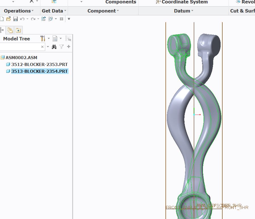
The satisfaction fades however as I see that my model is precisely the way it mirrored before. See picture below.
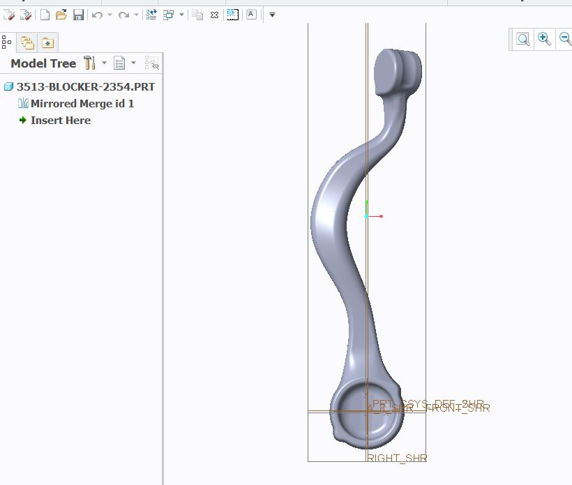
After the ensuing frustration I discovered that I could rotate my part so I was able to get the correct orientation. See picture below.
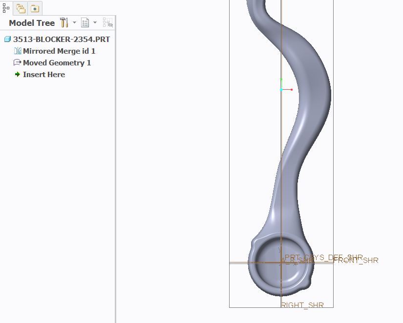
When I go back into Assembly after rotating the part I see that it displays incorrect to the view visibility within the part. See below picture
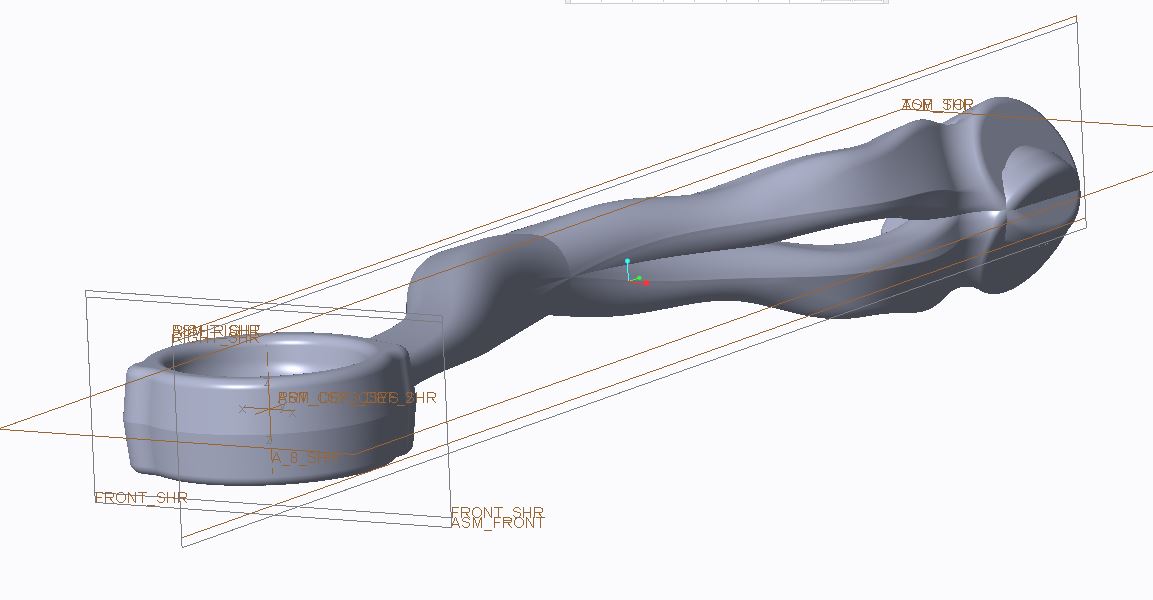
Any idea as to why my Part and Assembly models do not line up?
After this experience I voted up one of the Mirror part with specified plane Idea submissions.
What worries me however is that I have a mismatch between what I can view between Part and Assembly. This could lead to extremely expensive manufacturing results.
I did modify my planes to a World View Coordinate System. My views and Csys orientations appear to agree with each other in my Part and Assembly templates. This is the 1st such anomaly I've seen.
This thread is inactive and closed by the PTC Community Management Team. If you would like to provide a reply and re-open this thread, please notify the moderator and reference the thread. You may also use "Start a topic" button to ask a new question. Please be sure to include what version of the PTC product you are using so another community member knowledgeable about your version may be able to assist.
Labels:
- Labels:
-
2D Drawing
39 REPLIES 39
Feb 20, 2015
06:55 AM
- Mark as New
- Bookmark
- Subscribe
- Mute
- Subscribe to RSS Feed
- Permalink
- Notify Moderator
Please log in to access translation
Feb 20, 2015
06:55 AM
David,
I'm sorry my definition of the mirror issue was not clear to you. I will attempt to do better with explaining issues in the future.
As far as the Z direction is concerned I should have specified positive Z direction as pointed out by the direction of the CSYS arrows which are hard to see.
Still I must say that Creo's attempt to make it look like you have the mirror that you want only adds work to the process. To sort out the view directions in the new part is not a simple process. Besides changing every view to be aimed the correct way you also have to sort out sketch orientations because they get screwed up as well. When you are done with this process then you have to rotate the part into correct position. All of this adds work that doesn't need to be added. In the other CAD system that our company uses it takes 10 seconds to get a correct mirror with no extra complications added. If Creo can successfully mirror a part (using our world view coordinate system) in the Z plane, why can't it also mirror a part in the Y plane.
I have discussed the mirroring issue with PTC support. Their response to this issue was as follows.
I investigated the issue and found
similar issues were reported earlier to R&D as SPR.
The SPR 2118366 is under consideration by Product Line Management.
Feb 20, 2015
01:03 PM
- Mark as New
- Bookmark
- Subscribe
- Mute
- Subscribe to RSS Feed
- Permalink
- Notify Moderator
Please log in to access translation
Feb 20, 2015
01:03 PM
In the image the red arrow is pointing the same way as the positive Z? Which way are positive X and Y?
This will help understand changing view orientations Creating View Orientations in Creo Parametric - YouTube
As far a sketch orientation goes, PTC took a shortcut to creating mirror parts and features a long time ago and are unlikely to change it now. It's a complicated problem to resolve without using a left-hand coordinate system for some parts. If they did you could not assemble using default because the global coordinate systems can't be aligned.
In Creo creating a correct CSYS reference will resolve your assembly process.
Feb 20, 2015
01:29 PM
- Mark as New
- Bookmark
- Subscribe
- Mute
- Subscribe to RSS Feed
- Permalink
- Notify Moderator
Please log in to access translation
Feb 20, 2015
01:29 PM
In the image that I show the positive Z in the bottom direction (which is into the screen) the other positive directions would be "X" in the left direction and "Y" would be in it's normal position which would be towards the top of the screen.
If you have Creo 3 installed I have a model file of a simple part that I created using our start part.
There aren't any apparent issues with this template, but if someone finds an issue with my views it would be very helpful.
I built the start part in the world coordinate system as it reflects our needed downstream orientations.
Mar 27, 2015
05:18 PM
- Mark as New
- Bookmark
- Subscribe
- Mute
- Subscribe to RSS Feed
- Permalink
- Notify Moderator
Please log in to access translation
Mar 27, 2015
05:18 PM
A mirror is a mirror geometrically speaking. However if you are concerned with assembly placement of the mirrored object you can capture this by using this method. You need Advanced Assembly to do this.
1. Create a new part (this will become your mirrored part)
2. Use copy geometry feature to copy surfaces from original side into your new model (use "solid surfaces" selection to grab all solid data)
3. Mirror the copy geometry quilt around your mirror plane of choice
4. Solidify the mirrored quilt.
5. Hide the copy geometry feature.
This is a work around I have been using the last few years.
Nov 29, 2016
07:02 AM
- Mark as New
- Bookmark
- Subscribe
- Mute
- Subscribe to RSS Feed
- Permalink
- Notify Moderator
Please log in to access translation
Nov 29, 2016
07:02 AM
This is what i like in creo! 
If we can do a job whith 5 operations, why should we do it in 1 operation...?
Work arounds, work arrounds, and if somebody fix this and dot. Everibody work faster.
Nov 29, 2016
11:47 AM
- Mark as New
- Bookmark
- Subscribe
- Mute
- Subscribe to RSS Feed
- Permalink
- Notify Moderator
Please log in to access translation
Nov 29, 2016
11:47 AM
Yes, and I actually do the same steps as what Corey does and add steps by doing remove operations. Maybe it's just me but it worries me to hide something instead of completely removing it.
Nov 29, 2016
11:38 AM
- Mark as New
- Bookmark
- Subscribe
- Mute
- Subscribe to RSS Feed
- Permalink
- Notify Moderator
Please log in to access translation
Nov 29, 2016
11:38 AM
I avoid this by mirroring within the part itself, and creating a family table instance of left and right. This way, I get to choose the mirror plane, and there are ZERO external refs. I'll post more when I get time.
Nov 29, 2016
11:48 AM
- Mark as New
- Bookmark
- Subscribe
- Mute
- Subscribe to RSS Feed
- Permalink
- Notify Moderator
Please log in to access translation
Nov 29, 2016
11:48 AM
That would certainly be different than what our work flow presently is but that is an intriguing idea Frank. I'd like to see how you do this.
Nov 29, 2016
12:25 PM
- Mark as New
- Bookmark
- Subscribe
- Mute
- Subscribe to RSS Feed
- Permalink
- Notify Moderator
Please log in to access translation
Nov 29, 2016
12:25 PM
1. Create the datum plane you want to mirror about
2. Copy "All Solid Surfaces".
3. Mirror that copy.
4. Solidify "Cut" to remove the first part.
5. Solidify "Solid" the mirrored surfs copy to get the other side.
They will automatically update as long as any new features are added BEFORE step 2. You can differentiate the copy from the original by placing added features any time AFTER step 3.
It works great and is simple, although if you went wild with differences from the original to the copy the Family Table could get interesting, but..... So far, I have had no issues with it.
Dec 05, 2016
01:54 PM
- Mark as New
- Bookmark
- Subscribe
- Mute
- Subscribe to RSS Feed
- Permalink
- Notify Moderator
Please log in to access translation
Dec 05, 2016
01:54 PM
This is somewhat similar to what I do with some exceptions. I will have to try this out to see how the variation works. I never considered doing a solidify cut to remove the other part; if it works with my parts it would be simpler than doing removes.
Mirrored parts for us have separate job numbers; I'm not sure how this work in the way our work flows but it is something to consider depending on how much work it might save. There may be mistake potential due to the separate job numbers in the same base model (within the family table).
- « Previous
-
- 1
- 2
- Next »


