Community Tip - Did you know you can set a signature that will be added to all your posts? Set it here! X
- Community
- Creo+ and Creo Parametric
- 3D Part & Assembly Design
- Re: Motion skeleton - creating sketch rules
- Subscribe to RSS Feed
- Mark Topic as New
- Mark Topic as Read
- Float this Topic for Current User
- Bookmark
- Subscribe
- Mute
- Printer Friendly Page
Motion skeleton - creating sketch rules
- Mark as New
- Bookmark
- Subscribe
- Mute
- Subscribe to RSS Feed
- Permalink
- Notify Moderator
Motion skeleton - creating sketch rules
Hello,
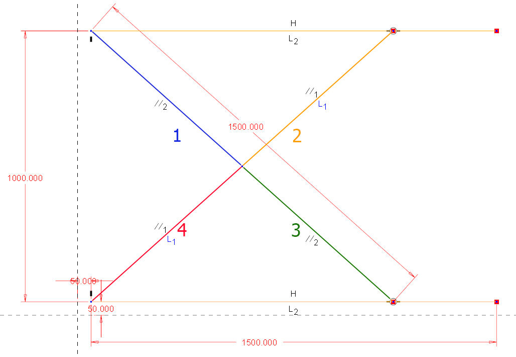
I want to use a motion skeleton in my design. I want to create mechanism like on the attached picture. I created body skeletons for all the bodies. GND, PART A, B, C. When I assign connection for body skeletons (In body definition dialog - not manually in component placement dialog) Creo doesn't recognise the mid pin. The two left PINs and Bearings are no problem but the center one. I tried to add circle to both PART A and PART B but unsuccessfull. I found in some training manual this:
After creating the motion skeleton assembly, you create a sketch. The sketch
must represent the following:
• The Ground Body – This is a non-moving component.
• Any Mechanism Bodies – Any moving part in the mechanism.
• Joint Connections, which are as follows:
– Pin joints can be defined at entity intersections or at circle centers.
– Slider joints can be defined from overlapping lines.
– Bearing joints can be defined where a line meets a non-endpoint location of another line.
– A Slot connection can be defined where a line endpoint lies on an arc or circle.
– Ball and Cylinder joints can be selected at locations where a Pin joint is found.
The entity intersection doesn't works, or I don't understand the meaning of this. Is there something else that it is need to take into acount when creating sketch (e.g.the order of creating sketch entities?). Could please someone explain the logic how creo look for connections between bodies?
thanks.
Solved! Go to Solution.
Accepted Solutions
- Mark as New
- Bookmark
- Subscribe
- Mute
- Subscribe to RSS Feed
- Permalink
- Notify Moderator
Hello,
I don't know if it's the best way but you can divide the bodies A and B in 4 different segments.

And when you will add the body B you will see the pin connection.

Check if it's normal there is more than one pin connection.
In any case it's works fine (see video) ![]()
Stéphane
- Mark as New
- Bookmark
- Subscribe
- Mute
- Subscribe to RSS Feed
- Permalink
- Notify Moderator
Hi Michal...
The circle thing they show in the training guide is, in my experience, useless. You don't need all those circles to communicate you want a "pin" constraint. It's all about those rules you posted - these are the golden rules:
- Pin joints can be defined at entity intersections or at circle centers.
- Slider joints can be defined from overlapping lines.
- Bearing joints can be defined where a line meets a non-endpoint location of another line.
- A Slot connection can be defined where a line endpoint lies on an arc or circle.
- Ball and Cylinder joints can be selected at locations where a Pin joint is found.
Here are some things to check:
- Try eliminating the circle
- Try selecting the circle and making sure the center point lies on both the line "A" and "B". right now I don't see a constraint attaching it to "A". It's just sitting at the center point of "B".
- The line representing part "A" and "B" should not be split at the center point. The lines should just cross.
- Check to see if "Pin" is available as a drop-down choice when the connection is being made
- If it is NOT, see what IS available. This will provide a clue to how the sketch is being interpreted.
You're close - something simple is probably all you need to fix this thing! See if any of those comments above help out.
Thanks!
-Brian
- Mark as New
- Bookmark
- Subscribe
- Mute
- Subscribe to RSS Feed
- Permalink
- Notify Moderator
Hello,
I don't know if it's the best way but you can divide the bodies A and B in 4 different segments.

And when you will add the body B you will see the pin connection.

Check if it's normal there is more than one pin connection.
In any case it's works fine (see video) ![]()
Stéphane
- Mark as New
- Bookmark
- Subscribe
- Mute
- Subscribe to RSS Feed
- Permalink
- Notify Moderator
Of course this would work - but I regarded it as a change to the intent of the original author's model.
- Mark as New
- Bookmark
- Subscribe
- Mute
- Subscribe to RSS Feed
- Permalink
- Notify Moderator
Hello,
thanks for the responses.
The Stephane's solution works fine for me. I couldn't do it work without splitting the lines.
I have another question. I have now created body skeletons and want to attach a geometry to the bodies. When I create parts in assembly level I have option to attach them to the skeleton bodies. But I need to create subassemblies and to attach these subassemblies to the skeleton bodies. This option is not available in the assembly create dialog.
How to deal with this? Should I to constrain manually the subassembly to the body skeleton and then use copy geometry feature to get the geometry in the subasm??
Michal
- Mark as New
- Bookmark
- Subscribe
- Mute
- Subscribe to RSS Feed
- Permalink
- Notify Moderator
I think this seems like a reasonable approach. I have a complicated body skeleton I'm developing for a project now. I'll try this and see how it works. I haven't needed a very complicated substructure before with previous body skeletons.
Thanks!
-Brian
- Mark as New
- Bookmark
- Subscribe
- Mute
- Subscribe to RSS Feed
- Permalink
- Notify Moderator
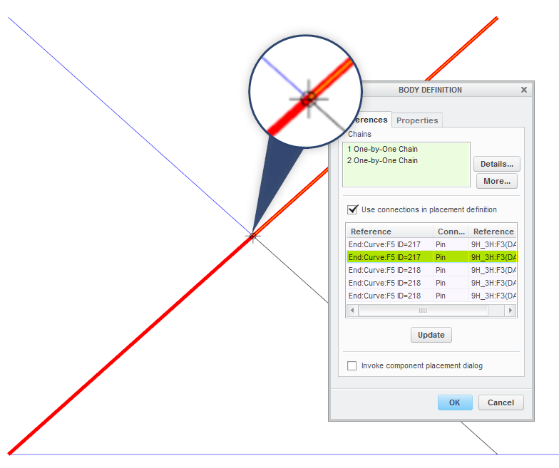
Ok, I stumbled on a problem: I created a body skeleton for one of the scissor-arms (as one line). Using the "update" button only brings up two bearing joints.
So, I changed the layout sketch and made split this line into two so that I can get at the middle pin joint.
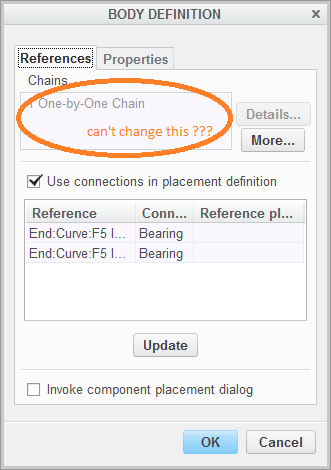
Now I want to re-define this body skeleton, but I get this grayed-out list:

The only way to proceed is to delete this skeleton part and start over from scratch?
Am I dumb and missing something, or this is how it is supposed to work (in that case, that's dumb...)
- Mark as New
- Bookmark
- Subscribe
- Mute
- Subscribe to RSS Feed
- Permalink
- Notify Moderator
Hi Paul...
I have NOT checked - but I seem to recall you get like, "one golden shot" to get it right and then you're stuck with the chain reference. When I had this same issue, I had to redo the body definition. I may have just been hacking through it and not paying attention but I know this happened a few weeks ago. It was early in my body definition so I didn't think much about it.
Maybe try right-clicking the feature in the model tree to see if "Edit References" is available? Let us know what you find.
Thanks!
-Brian
- Mark as New
- Bookmark
- Subscribe
- Mute
- Subscribe to RSS Feed
- Permalink
- Notify Moderator
Yeah, I gave up on this. It seems like a legacy feature from the days before. Do people still really do this - use these 2D sketch-driven mechanism skeletons?
If you know PTC's esoteric rules (which don't seem to work anymore - crossing the lines will not result in a pin joint!), you get to take a shortcut and some datums are automatically prepared for you. But if you change your mind, you go back to the real solution - so do some work up-front and prepare body skeletons with motion axes and planes and then assemble these body skeletons together using the mechanism constraints.
See Mechanism Design with Skeletons useing Top Down Design - YouTube
- Mark as New
- Bookmark
- Subscribe
- Mute
- Subscribe to RSS Feed
- Permalink
- Notify Moderator
Leo Greene = A Hack
![]()
KIDDING... just kidding people. I've seen this video before. Leo does an excellent job of breaking down a complicated process and making it look easy. He's one of the best at this. He was a founding member of PTC Community but hasn't been around in quite some time. I'm sure he's exceptionally busy helping people understand those 'esoteric' modeling rules.
Good luck, Paul - you're in the thick of it now for sure.
Take care...
-Brian


