
Turn on suggestions
Auto-suggest helps you quickly narrow down your search results by suggesting possible matches as you type.
Showing results for
Please log in to access translation
Turn on suggestions
Auto-suggest helps you quickly narrow down your search results by suggesting possible matches as you type.
Showing results for
Community Tip - You can subscribe to a forum, label or individual post and receive email notifications when someone posts a new topic or reply. Learn more! X
- Community
- Creo+ and Creo Parametric
- 3D Part & Assembly Design
- Need Help Modelling a Stent
Translate the entire conversation x
Please log in to access translation
Options
- Subscribe to RSS Feed
- Mark Topic as New
- Mark Topic as Read
- Float this Topic for Current User
- Bookmark
- Subscribe
- Mute
- Printer Friendly Page
Need Help Modelling a Stent
Mar 21, 2013
08:06 AM
- Mark as New
- Bookmark
- Subscribe
- Mute
- Subscribe to RSS Feed
- Permalink
- Notify Moderator
Please log in to access translation
Mar 21, 2013
08:06 AM
Need Help Modelling a Stent
Hi All,
I am new to Creo, but have done a bit of design (including stents) on Unigraphics/NX and Solidworks.
I am trying to model a stent (such as seen below) for export to Abaqus for FE and CFD.

I've tried a few different approaches, all that have ended up with me bashing my head on my desk from not understanding Creo's features.
My main strategy has been to start with a unit cell (or part of one), and tessellate it through the pattern function.
I start with a sketch of half a unit cell:

Then I sweep a rectangular cross section along the initial sketch. I then mirror the resulting solid twice to get the other half of the unit cell.

Then I make the unit into a pattern of 5x20 unit cells.

This is where things get messy (although this could be a symptom of doing something wrong earlier?). The cells don't quite align nicely - there is either overlap or underlap. I think the answer would be some kind of "unite" function, where the exterior surface would be saved from overlapping. There is a small 'lip' from where the unit cells don't quite align. I think I could fix this by either being more careful with the first sketch that the sweep was made with, or by adding rounds at this stage to "wipe" over them. When I try to add rounds at this point, the tool takes the edge as being for two separate solids.

I think the last step would be to use a Toroidal Bend to wrap the plane into a cylinder. This always fails when I try, and also fails with just the one unit cell. I am able to get it to roll with just a rectangular sheet, so I think I do know the tool well enough - I'm thinking its a problem with the solid I'm using?
Thanks for any help or advice!!
This thread is inactive and closed by the PTC Community Management Team. If you would like to provide a reply and re-open this thread, please notify the moderator and reference the thread. You may also use "Start a topic" button to ask a new question. Please be sure to include what version of the PTC product you are using so another community member knowledgeable about your version may be able to assist.
Solved! Go to Solution.
Labels:
- Labels:
-
2D Drawing
ACCEPTED SOLUTION
Accepted Solutions
Mar 21, 2013
10:59 PM
- Mark as New
- Bookmark
- Subscribe
- Mute
- Subscribe to RSS Feed
- Permalink
- Notify Moderator
Please log in to access translation
Mar 21, 2013
10:59 PM
I took the liberty of creating something like what you are trying to do. This is the in the same vane... patterned shape joined at opposite seam w/ control over the cylinder's radius which is variable in relations (defaults to the measurement between the two outside planes; original length). Limitations of the spinal bend forces you to work with a feature that entirely between the two outside edges or it will truncate the remaining feature. This is the reason for the extrude cut included to mate/match the seam.
The attached file is Creo 2.0 full version.
11 REPLIES 11
Mar 21, 2013
08:47 AM
- Mark as New
- Bookmark
- Subscribe
- Mute
- Subscribe to RSS Feed
- Permalink
- Notify Moderator
Please log in to access translation
Mar 21, 2013
08:47 AM
Hi Graeham,
I'm struggling to see the detail of your images, because I don't have an MCADCentral account.
However, I'd be tempted a) to work in surfaces until very late, and b) to think of holes rather than the material between them.
How about:
- Extrude a tube (solid should be fine)
- Construct the surfaces that form one hole
- Copy those surfaces, then pattern the copy (this is a very fast and robust way to pattern geometry)
- Solidify (select Cut) the first copy, then ref-pattern the solidify
HTH!
Mar 21, 2013
09:26 PM
- Mark as New
- Bookmark
- Subscribe
- Mute
- Subscribe to RSS Feed
- Permalink
- Notify Moderator
Please log in to access translation
Mar 21, 2013
09:26 PM
I cannot see the images either, but from your explanation, I suspect there are some techniques that will help.
1st of all, mirroring twice seems odd since it appears to be a rotated copy from the icon image I can see. Second, patterns can do minor "deviations" if you do not control the origin of the pattern logically. It really depends on what type of patterning you plan to do. And of course, being careful with your sketches, sweep options, and even datum creations is critical to creating a good model. If something looks wrong, it likely is not meeting your intent.
Regardless of how you want to get there, for the purposes of FE or CFD, don't you want the most accurate model possible? I am suggesting working with sheetmetal to come up with what you want. You can use form features to create your cut-outs and you can bend and unbend at will to finish up whatever detail you need. Sheetmetal parts can also be converted back to normal parts if you find it necessary.
If you do stick with your current course, check out the spinal bend options. Several great posts here on the forum. You also have warp but I believe the spinal bend is more accurate and oddly, easier to manage.
Mar 21, 2013
10:59 PM
- Mark as New
- Bookmark
- Subscribe
- Mute
- Subscribe to RSS Feed
- Permalink
- Notify Moderator
Please log in to access translation
Mar 21, 2013
10:59 PM
I took the liberty of creating something like what you are trying to do. This is the in the same vane... patterned shape joined at opposite seam w/ control over the cylinder's radius which is variable in relations (defaults to the measurement between the two outside planes; original length). Limitations of the spinal bend forces you to work with a feature that entirely between the two outside edges or it will truncate the remaining feature. This is the reason for the extrude cut included to mate/match the seam.
The attached file is Creo 2.0 full version.
Apr 02, 2013
05:59 AM
- Mark as New
- Bookmark
- Subscribe
- Mute
- Subscribe to RSS Feed
- Permalink
- Notify Moderator
Please log in to access translation
Apr 02, 2013
05:59 AM
Thanks Antonius and Jonathan. I had tried some of these approaches but I guess I quit prematurely and I'm still learning the limitations and "tricks" to the various features.
Thanks so much for the help!
Apr 02, 2013
12:36 PM
- Mark as New
- Bookmark
- Subscribe
- Mute
- Subscribe to RSS Feed
- Permalink
- Notify Moderator
Please log in to access translation
Apr 02, 2013
12:36 PM
My pleasure 
May 08, 2013
11:27 AM
- Mark as New
- Bookmark
- Subscribe
- Mute
- Subscribe to RSS Feed
- Permalink
- Notify Moderator
Please log in to access translation
May 08, 2013
11:27 AM
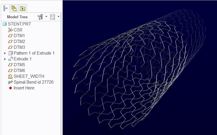
A follow-on to the original question.. I've got the general geometry, but there is a seam where the two ends of the flat sheet meet from the Spinal Bend. I believe there is two surfaces at each of these intersections, and it is giving me issues in Abaqus when I import via .STP. I can clean the geometry in Abaqus, but it is a convoluted process and seems like there should be a cleaner way to do this in Creo?
I'm thinking there must be an option when doing the spinal bend to merge the resulting ends? Or perhaps to merge/unite the seam that forms? .PRT attached to show the issue, its on the Z-axis. Thanks for any help!
May 08, 2013
12:12 PM
- Mark as New
- Bookmark
- Subscribe
- Mute
- Subscribe to RSS Feed
- Permalink
- Notify Moderator
Please log in to access translation
May 08, 2013
12:12 PM
I had a feeling that would come up. WF doesn't know to close ends of the spinal bend, though.
The idea behind part files in all Pro/E products is that as long as the solid features overlap, they become one part. The stent, fully rolled, is still one part.
However, you might be able to make a pattern and rotate the stent to where it mates perfectly and overlaps the seam, making a copy over the seam and forcing the join. Because spinal bends are special features, this may or may not work. I'll give it a try later today to see.
There are other methods that I am not certain are supported by WF although they should be.
I'll see what I can find.
May 08, 2013
02:48 PM
- Mark as New
- Bookmark
- Subscribe
- Mute
- Subscribe to RSS Feed
- Permalink
- Notify Moderator
Please log in to access translation
May 08, 2013
02:48 PM
Sorry but I cannot read your student version file.
I did some testing and although this should be a no-brainer, it is indeed a brain-teaser to remove the seam.
I tried patterning the geometry... no go! It works if I don't overlay the geometry "perfectly" but once I adjust the pattern to overlap, it fails no matter what I do.
So I try the next trick; there is a merge/inheritance feature through an assembly process. That too is a huge overhead and oddly enough, when two inheritance features are added to a new part file, it maintains the faint remnant of a seam when exported to STEP. I have attached the file to see if it works for you, but overall, I am not satisfied with this solution either.
In the attached file, I cut away 170 degrees of the original spinal bend; assembled 2 copies into an assembly file, one rotated so the two overlapped properly; I added a new empty file, activated the empty file in the assembly, and use the "Get Data > Merge/Inheritance" feature for each assembled stent. This copies a dependent copy of each assembled part into the new part. It is unclear if the merged features indeed create a single part. When you investigate the exported STEP file, it has a silhouette seam where the two merged objects come together. Further investigation with the data doctor shows that there is a surface at the interface of the two components.
So you will have to text the attached step to see if this is usable. It may import better in different programs.
May 08, 2013
09:47 PM
- Mark as New
- Bookmark
- Subscribe
- Mute
- Subscribe to RSS Feed
- Permalink
- Notify Moderator
Please log in to access translation
May 08, 2013
09:47 PM
Not all this works goes to waste 
May 09, 2013
06:28 AM
- Mark as New
- Bookmark
- Subscribe
- Mute
- Subscribe to RSS Feed
- Permalink
- Notify Moderator
Please log in to access translation
May 09, 2013
06:28 AM
Thanks so much!
I found a slightly different method that seems to be working well.
I took a 1/4 section of the stent, away from the seam, and imported that to Abaqus. I had to merge the faces within Abaqus between each of the four sections. Not as elegant of solution as I'd hoped but the resulting mesh is quite nice.
Nice stent-art! 
May 09, 2013
08:31 AM
- Mark as New
- Bookmark
- Subscribe
- Mute
- Subscribe to RSS Feed
- Permalink
- Notify Moderator
Please log in to access translation
May 09, 2013
08:31 AM
Hello, Douglas,
I enclose a link to the topic by doing other software, if it can help you.
Cordially.
Denis.


