Turn on suggestions
Auto-suggest helps you quickly narrow down your search results by suggesting possible matches as you type.
Showing results for
Please log in to access translation
Turn on suggestions
Auto-suggest helps you quickly narrow down your search results by suggesting possible matches as you type.
Showing results for
Community Tip - You can change your system assigned username to something more personal in your community settings. X
- Community
- Creo+ and Creo Parametric
- 3D Part & Assembly Design
- Re: PTC Tutorial on Createing Associated Peramiter...
Translate the entire conversation x
Please log in to access translation
Options
- Subscribe to RSS Feed
- Mark Topic as New
- Mark Topic as Read
- Float this Topic for Current User
- Bookmark
- Subscribe
- Mute
- Printer Friendly Page
PTC Tutorial on Createing Associated Peramiters: I need a bit of clarification
May 10, 2017
04:41 PM
- Mark as New
- Bookmark
- Subscribe
- Mute
- Subscribe to RSS Feed
- Permalink
- Notify Moderator
Please log in to access translation
May 10, 2017
04:41 PM
PTC Tutorial on Createing Associated Peramiters: I need a bit of clarification
PTC Tutorial on Creating Associated Parameters: I need a bit of clarification
Here are the specific instructions from PTC Support on:
How to create an Assembly Level Relation that controls the variable parameter value defined under a flexible Component in Pro/ENGINEER, Creo Elements/Pro and Creo Parametric.
------------------------------------------------------------------
- Create a parameter, in the part model and name it asm_param.
- In the assembly select the component and Right Mouse Button > Make Flexible.
- Add the part parameter asm_param; click Set Displayed Columns in the Varied Items dialog. Add the Assoc. Param column and click Ok. Type asm_param as the Associated Parameter for the added parameter, and click Ok.
- Create an assembly parameter named param. Then create an assembly relation as follows:
asm_param:FID_#=param
Where :
- asm_param is the Associated Parameter
- # is the feature id of the component
param is the assembly level (driving) parameter
----------------------------------------------------------------------------------
Item1) and Item 2) are clear enough.
Item 3) is a bit nebulous to me.
What is to be done in the "New Values" column?
Item 4) is also a bit confusing.
The relation uses the FID, which id a Feature ID.
What do you write to actually drill down to the dimensions inside the feature?
If I have two dims to family table, I would assume that I would need to parameters, correct?
I would also think that I would need two relations, one for each dimension, again, correct?
Etc., etc., etc.
This step needs a lot of clarification for me to truly grasp it.
Labels:
- Labels:
-
2D Drawing
40 REPLIES 40
May 10, 2017
09:18 PM
- Mark as New
- Bookmark
- Subscribe
- Mute
- Subscribe to RSS Feed
- Permalink
- Notify Moderator
Please log in to access translation
May 10, 2017
09:18 PM
Regarding item 3)
at the point when you defined the associated parameter, the "*" in the "New Values" column should change to the value in the base model (in the case of dimensions).
And as you found out in the other thread (Flexibility: One of two varied items gets locked. (Why?)) you shouldn't leave it set to "*"
Regarding item 4)
Each thing you plan to "control" has to have an associated parameter. That is the mechanism through which Creo communicates which "instance" of a component in an assembly is being "changed" from its base version. Note that the names of these parameters do not have to be unique, meaning that if you have 3 flexible "rods" assembled, each can have associated parameters called "LENGTH" and "DIAMETER".
The relations that control flexible components can be composed at the assembly relation level. It is easiest to do so by using that [] icon in the relation editor (the "insert parameter" function). When you launch it, change to look in "component" and select the flexible component, and then you will have the table with the associated parameters you defined for it and be able to insert the proper "code" into the assembly level relations. So you see how the FID_# syntax identifies what component instance will be "changed".
Note that relations can also be written at the component level: launch relation editor, Look In "Component", select the flexible component, and then you will see the associated parameters listed in the "Local Parameters" section. Also, you will notice that the FID_# syntax will not be present in component relations - because the system already knows what component will be "changed".
Hope this clarifies things a bit...
May 11, 2017
08:21 AM
- Mark as New
- Bookmark
- Subscribe
- Mute
- Subscribe to RSS Feed
- Permalink
- Notify Moderator
Please log in to access translation
May 11, 2017
08:21 AM
Thanks for that Paul,
So, does the FID_# simply tell the editor which feature to look in?
Then at that point, can the dimensions be selected?
May 11, 2017
08:37 AM
- Mark as New
- Bookmark
- Subscribe
- Mute
- Subscribe to RSS Feed
- Permalink
- Notify Moderator
Please log in to access translation
May 11, 2017
08:37 AM
The :FID_# syntax tells the system, not the editor, how to regenerate the model...
I don't understand your question about the point at which dimension can be selected. That is done when either making the component flexible in the assembly, or when predefining the flexiblity at the part level...
May 11, 2017
04:18 PM
- Mark as New
- Bookmark
- Subscribe
- Mute
- Subscribe to RSS Feed
- Permalink
- Notify Moderator
Please log in to access translation
May 11, 2017
04:18 PM
My question is with regard to writing the relation or relations.
The FID_# notation is for a feature, but I am asking about the dimensions inside the feature.
Ok, is there a parameter for each varied item, in this case, each of the two dimensions?
Then, is there a separate relation for each varied item, again, in this case, each of the two dimension?
If their are separate parameters and relations for each of the two dimensions, the FID_# would not seem to me to be able to get to them, as it is looking at the single feature level that contains these dimensions.
This part is just not clear to me.
May 11, 2017
06:22 PM
- Mark as New
- Bookmark
- Subscribe
- Mute
- Subscribe to RSS Feed
- Permalink
- Notify Moderator
Please log in to access translation
May 11, 2017
06:22 PM
Oh, I think I see the source of confusion. FID_# is not the ID of the feature that contains the dimensions. It is the ID of the flexible component in an assembly (think of a component as a kind of a "feature" in an assembly context).
You can configure your model tree columns to display feature IDs:
(note how both instances of the flexible component "TEST_ROD" have associated parameters "VARIED_LENGTH" and "VARIED_DIAMETER" defined)
May 12, 2017
10:11 AM
- Mark as New
- Bookmark
- Subscribe
- Mute
- Subscribe to RSS Feed
- Permalink
- Notify Moderator
Please log in to access translation
May 12, 2017
10:11 AM
Got it.
Yes, I look at components in an assembly as assembly features as well.
I just wasn't putting that together.
So then, based on what I see here, would I need to have a base part for each family table instance?
That is still not clear to me.
Also what would be in the Varied Items list for the part flexibility in the assembly?
For Item 4 in the tutorial: asm_param:FID_#=param:
Are "VARIED DIAMETER" and VARIED LENGTH" the parameters that you added in your base part, i.e. "asm_param_1" and "asm_param_2"?
Are "50 and 25" the data for your diameter "param"?
Are "100 and 225" the data for your length "param"?
I really don't get why there are two base parts, FIDs 5401 and 5637, in your assembly.
I a base bart copy required for each family table instance?
Further: Both show flexibility in the icon, but only 5401 says "FLEXIBLE COMPONENT" under it, where 5437 does not.
May 12, 2017
11:27 AM
- Mark as New
- Bookmark
- Subscribe
- Mute
- Subscribe to RSS Feed
- Permalink
- Notify Moderator
Please log in to access translation
May 12, 2017
11:27 AM
Ok, this has taken me few years to understand, and I think maybe my example screenshot is too complicated, but I'll try to rescue it by providing explanations:
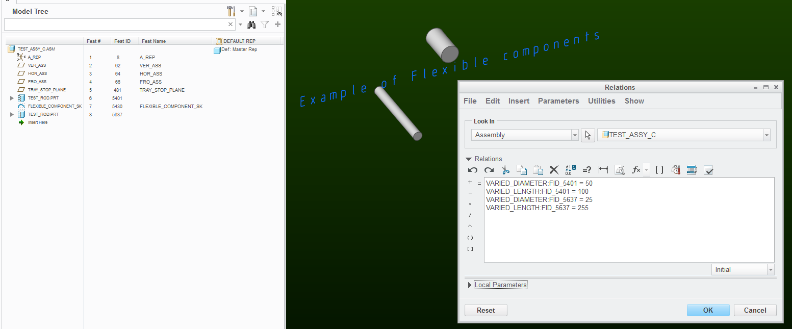
1) Please examine the screenshot more closely. "5401" does not say "FLEXIBLE COMPONENT". I think you are reading the name of an assembly level feature (namely the sketch called "FLEXIBLE_COMPONENT_SK". I added this sketch to show how in assemblies, both the components and features are numbered and referenced using FIDs.
2) The relations window shows the assembly level relations.
3) The shown assembly has two instances of a flexible component (same base model called "TEST_ROD"); this is just for example's sake, in order to illustrate how multiple instances of the same base model can made to assume different shapes within the same assembly.
4) The varied items table was defined in the base part "TEST_ROD" and it has two rows - the dimensions for the diameter and length of the cylindrical feature.
5) Associated parameters are not added to the base part. They are added to the flexible assembly component via the Variable Items table.
6) In both component definitions, the associated parameters are called "VARIED_DIAMETER" and "VARIED_LENGTH". This is not required, I could have called the associated parameters for the 1st rod "VARIED_DIAMETER_1" and "VARIED_LENGTH_1" and for the 2nd rod "VARIED_DIAMETER_2" and "VARIED_LENGTH_2"
If I did that, then accordingly, my assembly relations would look different:
VARIED_DIAMETER_1:FID_5401 = 50
....
VARIED_DIAMETER_2:FID_5637 = 25, etc...
7) I am confused about your repeated questions regarding requiring a base part for each family table instance, etc..., because really, this discussion and my example has nothing to do with family tables...
In fact, flexible components should be used judiciously and their use should be planned out, as there are limitations and pitfalls to their use. Although in a way, a flexible component is a "behind-the-scenes family table instance" of a base part, it really shouldn't be used in the same way.
Essentially, the "flexible component instance" only exists in one assembly, whereas a family table instance can exist in multiple assemblies.
There is a kind of a way "wrap" a family-table assembly around a flexible component in order to be able to reuse it in multiple models, but then why not just have a family table in the base model???
-
An iconic! example of a spring comes to mind - you buy 10 springs (same P/N), install them in 10 places; you don't buy 10 compressed spring installations...
May 12, 2017
12:44 PM
- Mark as New
- Bookmark
- Subscribe
- Mute
- Subscribe to RSS Feed
- Permalink
- Notify Moderator
Please log in to access translation
May 12, 2017
12:44 PM
OK, we are having a severe disconnect here.
Regarding your Item 5: I realize that the associated parameters are added at the assembly level. when bringing in the a part, and I believe that I have always referenced the varied items window, when bringing the part into the assembly, whenever referring to adding the "Associated Parameters". I have just not understood how they relate to the actual part dimensions.
However, the tutorial states in Item 1, to create a parameter called "asm_param" in the part model.
Further, in Item 4 of the tutorial, the relation, given, begins with "asm_param" as the very first expression, hence my question about asm_param_1 and asm_param_2 regarding "VARIED_DIAMETER" and "VARIED_LENGTH", which are the very first expressions, in your relations.
Again, back in the tutorial, the very first expression is "asm_param", set up at the part level per tutorial Item 1.
Regarding your Item 7: You ask why I am discussing family tables.
I must apologize for not stating, at the beginning of this thread, that I am working with family table assemblies. That was the whole idea in my earlier thread regarding "One Varied item Getting Locked".
While this is a specific thread about the Associated Parameters Tutorial, it is still with total regard to the family table issue from the earlier thread, but again, I failed to let you know that.
---------------------------------
The reasons that I am using family table assemblies, rather than family tabling at the part level, are as follows:
Currently I have one base part model and two assembly models, one assy model for the completed raw material length assy, and the other assy model for the finished cut length assy.
I use the, single, base part in both family table assemblies.
NOTE: I have to make the parts flexible, in order to reach down, in the assy, to the part level, and activate the Length and Diameter dimensions when adding them, as columns, in the assy family table. If they are not made flexible, they can not be activated and displayed for selection and addition, as columns, to the family table.
If I were to family table these items at the base part level, I would need two, part models, one for the family tabled raw material lengths, and one for the family tabled cut piece lengths.
Then I would also need to make separate models for each of the cut piece assemblies.
In this case, rather than having only 3 models, I would need to create a minimum of 18 models, and most likely many more, as we add more raw material diameters, and more cut piece lengths to the tables.
As I have mentioned, I need to make the finished raw material and cut piece length parts as assemblies of the base part and a bulk part, so that I can populate the quantity column of the automated BOM Table that we bring into our drawing from the bulk part.
May 12, 2017
01:40 PM
- Mark as New
- Bookmark
- Subscribe
- Mute
- Subscribe to RSS Feed
- Permalink
- Notify Moderator
Please log in to access translation
May 12, 2017
01:40 PM
Well, as usual, PTC instructions are for the most part correct and at the same time very confusing.
Concerning item #1 of the tutorial, the choice of naming this part level parameter as "asm_param" is very unfortunate. Which is why I think you are glossing over is the step #3 of the tutorial, which tells you to create an associated parameter called "asm_param" for the flexible component's varied parameter called "asm_param" 
Clear, huh?
I think the example would have been clearer if in step 1) you were told to create a parameter in the base model called "part_parameter"
In Step 3), you add "part_parameter" to the varied items table (in the parameters tab), and then create an associated parameter for it called "varied_part_parameter"
Then in Step 4) you can write an assembly level relation "varied_part_parameter:fid_# = param"
----
It seems like using flexible components is the right strategy in your application, as you end up controlling everything from one place, and the resulting representation of the physical object is an instance of family-tabled assembly. I just wanted you to know that flexible components have caveats, that's all. For example, I am right now working on an assembly where I am trying to make an assembly level cut through one of these flexible components, and guess what? - Creo doesn't seem to want to cut through these things.
May 12, 2017
02:19 PM
- Mark as New
- Bookmark
- Subscribe
- Mute
- Subscribe to RSS Feed
- Permalink
- Notify Moderator
Please log in to access translation
May 12, 2017
02:19 PM
First of all, I sincerely appreciate your patience with trying to helping me understand this very confusing aspect of CREO.
I know that my last message might have looked somewhat confrontational, and I was marginally concerned that you might take it a bit that way, but it was the only way that I could think to write it, and to be absolutely clear on all points.
I want to thank you for taking it just as it was intended; clear concise information, and not in any way a confrontation.
Now I am not saying that it was clear and concise, but only that it was intended that way. LOL
----------------------------------------
OK then, all that said:
----------------------------------------
Your explanation is a lot clearer, but I did sort of follow the asm_param thing from the part to the assembly, nebulous as it is.
The part that I was missing is that you can actually create the Associated Parameters in the parameters tab of the varied items window, and that you need to do that in order to have the required parameters at both ends of the relation.
This, of course, made the relation very hard for me to comprehend.
There are a couple of confusions still, however.
1) From your example above, in your explanation of Tutorial Item 4, when you wrote the relation at the end ( "varied_part_parameter:fid_# = param" ) shouldn't param, at the end, actually be part_parameter?
Also, using the flexible part, the way that I did, and then using it with flexibility in a family table, do I need to even consider the associated parameter issue?
It seems that the associated parameters are more for use in the situation where you need to have several copies of the same flexible part in the same assembly, and in different configurations, like maybe a given spring at various levels of compression or tension, or maybe a label wrapped around different diameter components.
They don't seem to be for use in the situation where you need completely unique, but very similar, parts for use as uniquely named or numbered components.
If associated parameters would help here I am not sure how.
Can you clear this up at all, or am I just going down a rabbit hole?
May 12, 2017
03:37 PM
- Mark as New
- Bookmark
- Subscribe
- Mute
- Subscribe to RSS Feed
- Permalink
- Notify Moderator
Please log in to access translation
May 12, 2017
03:37 PM
1) From your example above, in your explanation of Tutorial Item 4, when you wrote the relation at the end ( "varied_part_parameter:fid_# = param" ) shouldn't param, at the end, actually be part_parameter?
Well, not at all. I was trying to keep the same nomenclature as in the quoted ptc tutorial, in which they explain that:
- asm_param varied_part_parameter is the Associated Parameter
- # is the feature id of the component
param is the assembly level (driving) parameter
So the relation I wrote:
varied_part_parameter:fid_# = param
sets the value of the parameter (for that flexible-component) to be equal to that of some assembly-level parameter.
In this way, the flexible component is "driven" by information from the assembly.
I don't think that what you suggested would ever be accepted by the system, because part_param exists in the part level, and we are talking about assembly level relations.
But something like this would work:
varied_part_parameter:fid_# = 1.23
in this case, the parameter in the flexible component will be set to equal to 1.23 (in this example, part_parameter is of type "real number")
varied_part_parameter:fid_# = "Hello!"
in this case, the parameter in the flexible component will be set to equal to string "Hello!" (in this example, part_parameter is of type "string")
varied_part_parameter:fid_# = some_parameter:22
in this case, the parameter in the flexible component will be set to equal to the value of the parameter called "some_parameter" in an assembly component whose session id is 22. (note that it is up to the user to ensure that types must match).
---
For your second question, I would submit that in your case, you had success; however, it came with some dubious work-around involving removing * values and in general, I think you were lucky. I just tried a toy example of trying to "redefine" an already saved assembly and turn it into a family-table driven version of what you accomplished, and I hit a brick wall. The family table seems to have been constructed, as I saved the assembly, I was asked to verify instances which I did. Upon opening any specific instance, I discovered all those IN_D_1:FIDxxx columns in the table had been deleted for me. I tried again but this time, I created the associated parameters, and things worked smoothly. So I strongly urge that you do not rely on the system to "auto-create" these things. Additionally, you miss the chance to properly annotate your model intent.
May 12, 2017
04:58 PM
- Mark as New
- Bookmark
- Subscribe
- Mute
- Subscribe to RSS Feed
- Permalink
- Notify Moderator
Please log in to access translation
May 12, 2017
04:58 PM
Where, in your example, did you create a parameter called "param"?
I simply to not see it.
I see your "part_param", which would be analogous to the tutorial's "asm_param" created in the actual part.
I also see your "varied_part_param", which seems to be analogous to the tutorial's "param" created in the assembly.
In the tutorial, the parameter from the part, "asm_param" is entered into the associated parameter column in the varied items window.
Then their relation says, and I copied and pasted this from above, "asm_param:FID_#=param".
This says that the part parameter, called "asm_param" will be equal to the assembly parameter, called "param".
Again, in your rendition, I do not see you setting a parameter called "param".
You enter "part_param" into the Associated Parameters column, which is the same as the tutorial entering "asm_param" there.
So then,
In order for your relation to read analogously to the tutorial relation, it would have to be "part_parameter:fid_#=varied_part_param".
BTW, I sent you a PM.
Let me know,
Roger
May 12, 2017
08:47 PM
- Mark as New
- Bookmark
- Subscribe
- Mute
- Subscribe to RSS Feed
- Permalink
- Notify Moderator
Please log in to access translation
May 12, 2017
08:47 PM
Ok, I think we should forget that horrible PTC tutorial example that started this confusion. I took some time to clarify and write down my thoughts on the matter.
---------
Background:
The configuration of a "flexible" component can be vastly different from its "base" model and is derived by the state of its variable items table.
The values in the variable items table can be specified in many ways:
1) They can be defined during the component definition process; however, such components are "static" and cannot be changed other through a "edit-definition" step.
2) For values of dimension items, a variety of measure-functions are available to generate them - this allows such flexible component to "dynamically" adapt to the assembly configuration.
3) Values can be adopted from associated parameters, which allows for automation through use of relations or family-tables.
With point #3 in mind, let us return to the original goal of the discussion: "How to create an Assembly Level Relation that controls the variable parameter value defined under a flexible Component in Creo Parametric. Note that family tables are not in the scope of this discussion.
I think that by following the steps below, you will gain an understanding of how and why these "associated parameters" work.
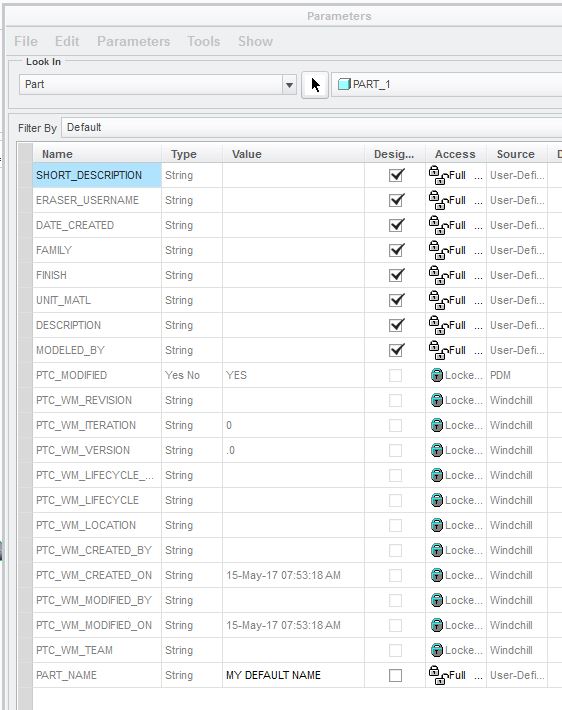
1) in part model part.prt, define a parameter; call it PART_NAME, make it of type STRING, and input a value: My Default Name
2) Start a new assembly, assy.asm.
3) Insert part.prt into assy.asm.
4) Insert another part.prt into assy.asm. Select this 2nd component, right-click on it, make flexible.
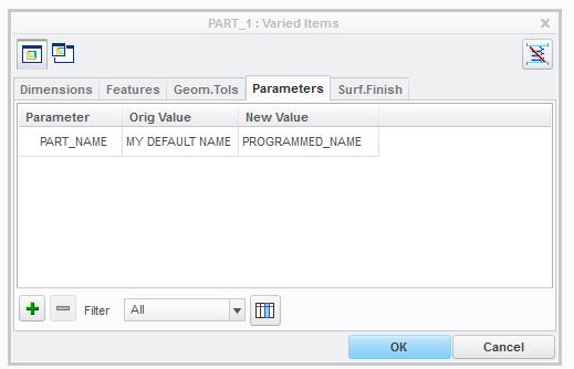
5) Varied items table appears. Switch to the "Parameters" tab. Add the parameter PART_NAME to the table. Now this makes it a variable parameter - meaning that the value of this parameter (for this component) can be different from the one defined in the base model. Type in the new value in the table: Changed Name
6) Accept the definition, and regenerate the assembly.
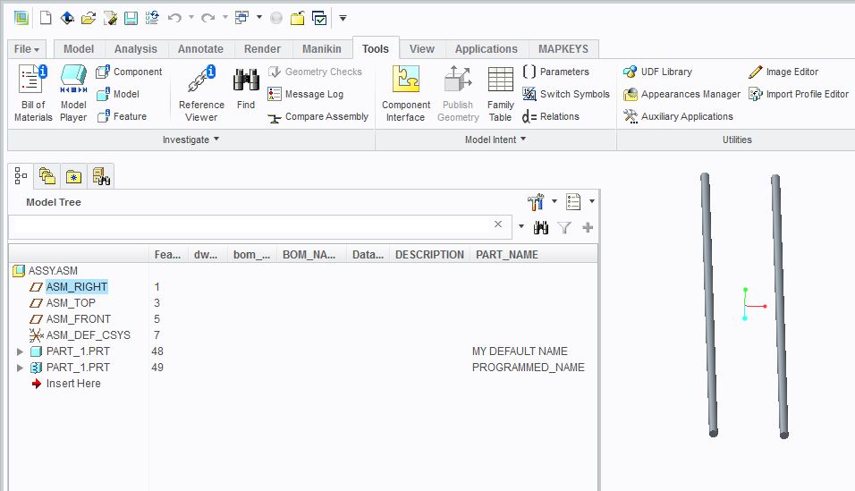
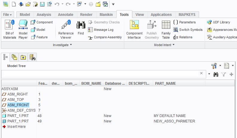
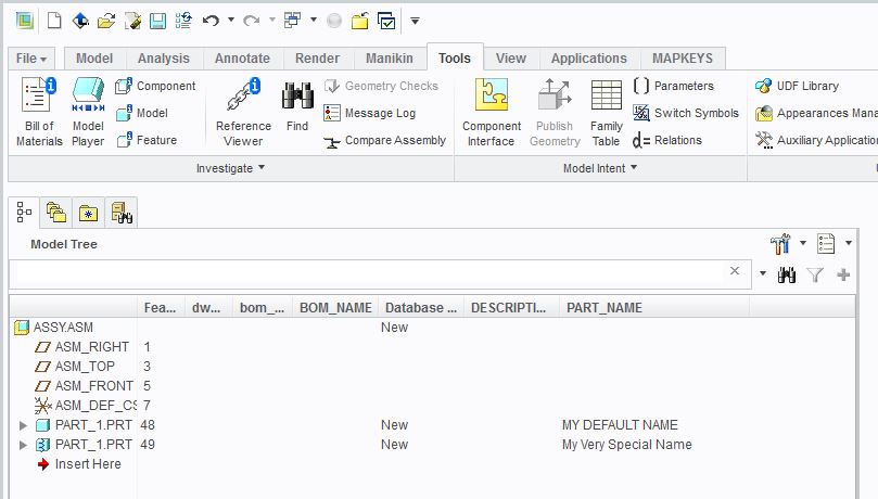
7) Let's show the value of the parameter PART_NAME for the components using the model tree. Click on that "hammer+screwdriver" icon in the upper right of the model tree and select "Tree Columns". In the "Not displayed" area, switch Type: to "Model Params", and then for Name:, type in PART_NAME Then click on >> to transfer it to the Displayed list. OK, and now you should see in the model tree the values of the parameter PART_NAME:
For the 1st part.prt, it says My Default Name
For the 2nd part.prt, it says Changed Name
This demonstrates that flexible components can adopt parameter values different from those defined in the original models.
Ok, but what we are really after is to be able to use a relation to change the value of the varied parameter PART_NAME in that 2nd part.prt
In order do to be able to do this, we first have to create an associated parameter for it:
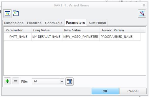
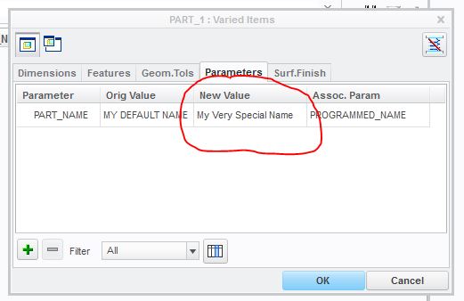
1) Edit the definition of the 2nd part.prt -> Flexiblity tab -> Varied Items table -> Enable the display of the Assoc. Param column.
2) Define the associated parameter by typing its name in the Assoc. Param column. Note that the name of the associated parameter can be anything you want - here is your chance to be descriptive. Let's call this associated parameter PROGRAMMED_NAME.
Accept the definition, and regenerate. So far, no changes are visible in the model tree. However, the 2nd part.prt now has a component-level parameter called PROGRAMMED_NAME. And you can see it and change its value: Tools->Parameters->Look In->Component->Select the 2nd part.prt
Change the value of this associated parameter and regenerate - note how this becomes the value of the parameter PART_NAME in the model tree.
This demonstrates how an associated parameter is a component-level parameter which value is adopted by an item in the variable items table defined for that flexible component. Thus the configuration of a flexible component is derived from the state of its associated parameters.
Ok, now, let's create a relation which will cause the PART_NAME of the 2nd part.prt to become My Very Special Name:
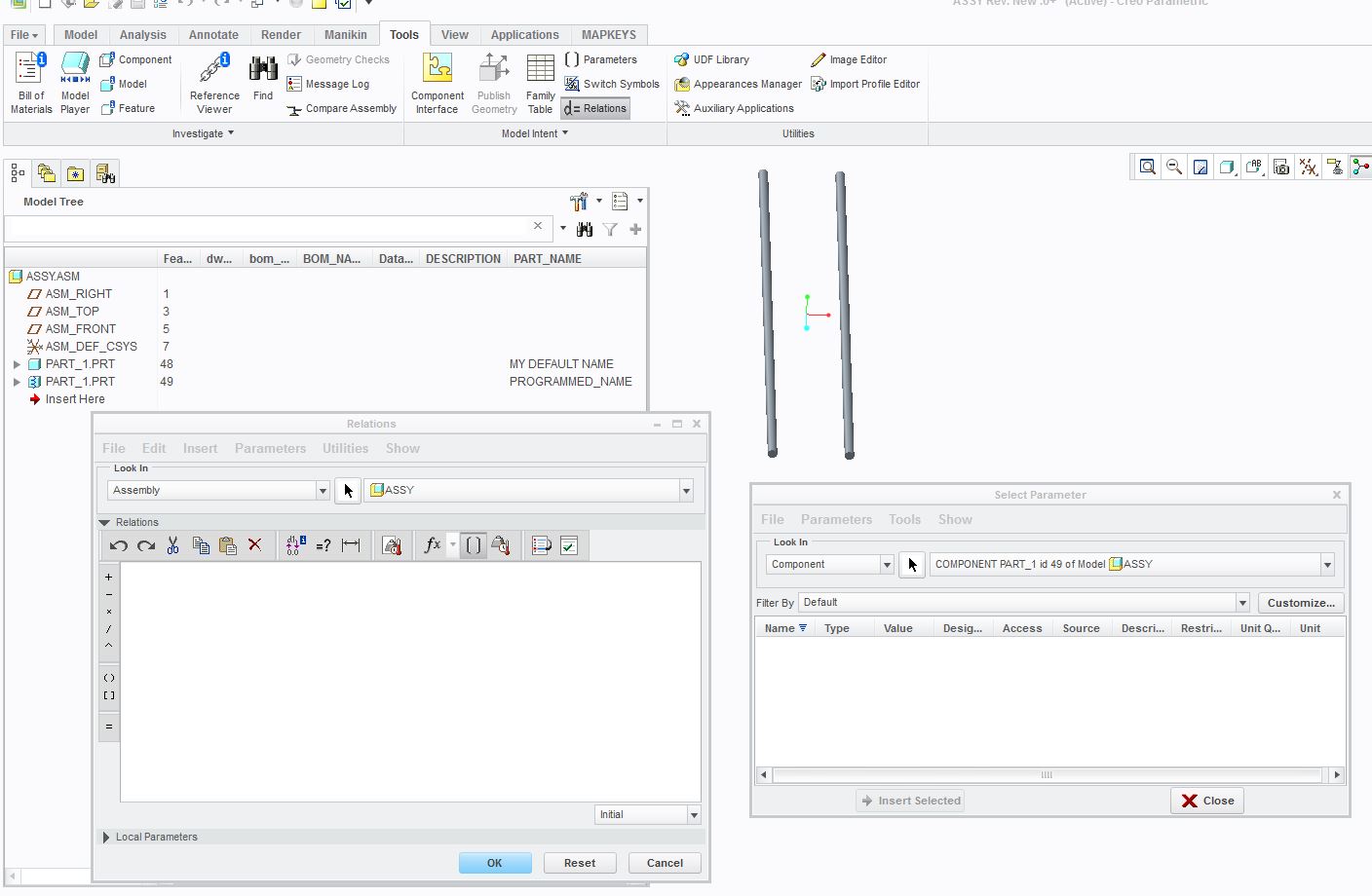
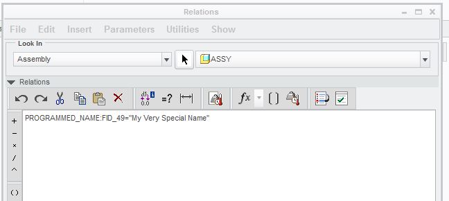
1) Open relations editor.
2) Fetch the name of the associated parameter by using the "Insert Parameter Name" function: Click on ([] icon) -> look in -> component -> select the 2nd part.prt
The table of component-level parameters appears; Select parameter PROGRAMMED_NAME and "Insert Selected".
4) The text PROGRAMMED_NAME:FID_# appears in the relations area (# is some number which is the feature ID of the 2nd part.prt)
5) Complete typing in the relation:
PROGRAMMED_NAME:FID_# = "My Very Special Name"
6) OK, Regenerate, and note how:
For the 1st part.prt, PART_NAME is My Default Name
For the 2nd part.prt, PART_NAME is My Very Special Name
In conclusion, the configuration of a flexible component can specified through the values of its associated parameters. Associated parameters are component-level parameters that control the values of the variable items in the flexible component's table in which they were defined. Moreover, the specification of associated parameter values does not require re-definition of their flexible-components and can occur manually (via manipulation of component-level parameter tables) or automatically (via relations).
May 12, 2017
09:41 PM
- Mark as New
- Bookmark
- Subscribe
- Mute
- Subscribe to RSS Feed
- Permalink
- Notify Moderator
Please log in to access translation
May 12, 2017
09:41 PM
This thread is making my head hurt.
I am trying to pick up why we're using flexible components and an assembly parameter to do what seems like we could do other ways with less headache. After a 16 hour shift, I am just not getting it. Have we exhausted inheritance features already?
I must be missing something major.
May 13, 2017
01:38 PM
- Mark as New
- Bookmark
- Subscribe
- Mute
- Subscribe to RSS Feed
- Permalink
- Notify Moderator
Please log in to access translation
May 13, 2017
01:38 PM
Hi Brian,
Thanks for reaching out.
What I am really trying to do is to bring a part (.prt) into an assembly, then control its length and diameter via the instances in a family table.
The only way, that I am aware of, to access these part level dimensions, in the assembly, is to make them flexible at the part level.
I then make the part flexible in the assembly, and change the values, in the new values column, from an asterisk to the original base part values.
The reason for the assembly is that a bulk part needs to travel with the base part for population of the BOM Table on the drawing.
The reason for doing the family table in the assembly, rather than in the part (.prt) is to keep from having to have separate assembly models for each length and diameter combination, of which there are many.
In another post that I made regarding the above, associated parameters became the hot topic of interest to achieve this.
However, when I found the PTC Tutorial on creating associated parameters, it made no sense to me, so I posted here regarding the tutorial, and that is how we got here now.
I am still not sold that associated parameters is the way to go.
I am all ears to anything you may have to share on the subject in this actual post.
May 13, 2017
01:43 PM
- Mark as New
- Bookmark
- Subscribe
- Mute
- Subscribe to RSS Feed
- Permalink
- Notify Moderator
Please log in to access translation
May 13, 2017
01:43 PM
Thanks Paul,
When I get to the office on Monday, I will try this out.
However, I am not sure how this solves my issue of the family table assemblies that I am working with
Yes, I know that family tables are not the focus in this thread, but it is what brought up the subject of associated parameters in the first place.
At the end of the day, that is what I need to boil down.
Again, I will try out your instructions on Monday, but I still don't necessarily understand what they are actually doing at the practical level.
I do appreciate your patience.
May 15, 2017
08:45 AM
- Mark as New
- Bookmark
- Subscribe
- Mute
- Subscribe to RSS Feed
- Permalink
- Notify Moderator
Please log in to access translation
May 15, 2017
08:45 AM
Hi there,
It is Monday morning and I am going thru your exercise.
All worked well up till the last part where you explain writing the relation.
I see both of the values under the Part_Name column in the assembly,
However, when I perform the look up to get the parameter Programmed_Name from the 2nd part.prt, the window is empty.
I did just as you directed me, several times.
-----------------------------------------
1) Open relations editor.
2) Fetch the name of the associated parameter by using the "Insert Parameter Name" function: Click on ([] icon) -> look in -> component -> select the 2nd part.prt
The table of component-level parameters appears; Select parameter PROGRAMMED_NAME and "Insert Selected".
--------------------------------
The problem is that at that point the component level parameter widow is empty.
Below is a screen shot of the assembly screen, showing My Default Name, and Programmed_name for the 1st and 2nd parts respectively.
When I follow the above noted instructions, the component level parameters window is empty.
I have also included a screen shot of that.
Assembly View
Relations Window and Component Level Parameters Window
May 15, 2017
09:27 AM
- Mark as New
- Bookmark
- Subscribe
- Mute
- Subscribe to RSS Feed
- Permalink
- Notify Moderator
Please log in to access translation
May 15, 2017
09:27 AM
Hmm, from the screenshots, I am concerned that you didn't follow the instructions at some point, because I'd expect the PART_NAME for the 2nd part_1.prt to display "Changed Name", and not "PROGRAMMED_NAME", in the assembly's model tree...
So please post the screenshot of the following tables this 2nd part_1.prt:
a) the table of component-level parameters
b) the "parameters" page of its variable items table
May 15, 2017
12:01 PM
- Mark as New
- Bookmark
- Subscribe
- Mute
- Subscribe to RSS Feed
- Permalink
- Notify Moderator
Please log in to access translation
May 15, 2017
12:01 PM
a) The component level parameters window from the 2nd part_1.prt is shown in my earlier post.
Here is the screen shot from the base part, otherwise I am not sure what you are asking for.
Varied Items window for 2nd part in assy
May 15, 2017
12:35 PM
- Mark as New
- Bookmark
- Subscribe
- Mute
- Subscribe to RSS Feed
- Permalink
- Notify Moderator
Please log in to access translation
May 15, 2017
12:35 PM
Right, I did see the empty table, but I wanted to make sure by asking for the component parameter table that you can display (according to my instructions) in this manner:
Tools->Parameters->Look In->Component->Select the 2nd part.prt
It seems to me that if you followed my instructions more carefully, you'd have seen that the component parameter table is empty before attempting to write any relations.
Moreover, I see from the screenshot of your var. items table that you have not created an Associated Parameter, and that is why the component parameter table is empty.
To be frank, I am ready to give up because I don't understand where your confusion originates, and I tried to be as explicit and clear as I can be in my "tutorial".
May 15, 2017
01:55 PM
- Mark as New
- Bookmark
- Subscribe
- Mute
- Subscribe to RSS Feed
- Permalink
- Notify Moderator
Please log in to access translation
May 15, 2017
01:55 PM
I apologize for making you want to pull you hair out.
You wrote:
Tools->Parameters->Look In->Component->Select the 2nd part.prt
That was how I accessed the component parameters window for the 2nd part.
Here it is again, with the associated parameter in place.
I thought that I had created it, but must not have.
It is there now, and it shows up in the 2nd part.prt parameters list
You will see that I renamed it to NEW_ASSO_PARAMETER
Here it is showing up in the assembly feature tree.
You wrote:
It seems to me that if you followed my instructions more carefully, you'd have seen that the component parameter table is empty before attempting to write any relations.
You are absolutely correct.
I went back and forth many times to make sure that I caught everything, but I sure must have missed a line or two.
Again, I was sure that I had created the Associated Parameter. I think I was a bit overwhelmed or confused at that particular moment. Now going back through and looking only for that spacific instruction, I see what I missed.
OK then:
Here is the relation window.
Here is the feature tree with the relation changing the name to "My Very Special Name"
Just for clarity, here is the new Varied Items Window:
May 15, 2017
02:09 PM
- Mark as New
- Bookmark
- Subscribe
- Mute
- Subscribe to RSS Feed
- Permalink
- Notify Moderator
Please log in to access translation
May 15, 2017
02:09 PM
Ok, I'm glad we got through it
These associated parameters - I still think they are very confusing, though after going through this discussion, I have a much better understanding of the subject.
May 15, 2017
04:40 PM
- Mark as New
- Bookmark
- Subscribe
- Mute
- Subscribe to RSS Feed
- Permalink
- Notify Moderator
Please log in to access translation
May 15, 2017
04:40 PM
OK, as I said earlier, I made a test rod part, and two assemblies analogous to my original project.
I set them both up the same way, with the acception of creating the associated parameters, as I did in the exercise that you had me do.
The part has parameters for Diameter and Length, and they are real numbers.
The assembly has associated parameters for Tabled Diameter and Tabled Length.
You can see that all is working as per the exercise.
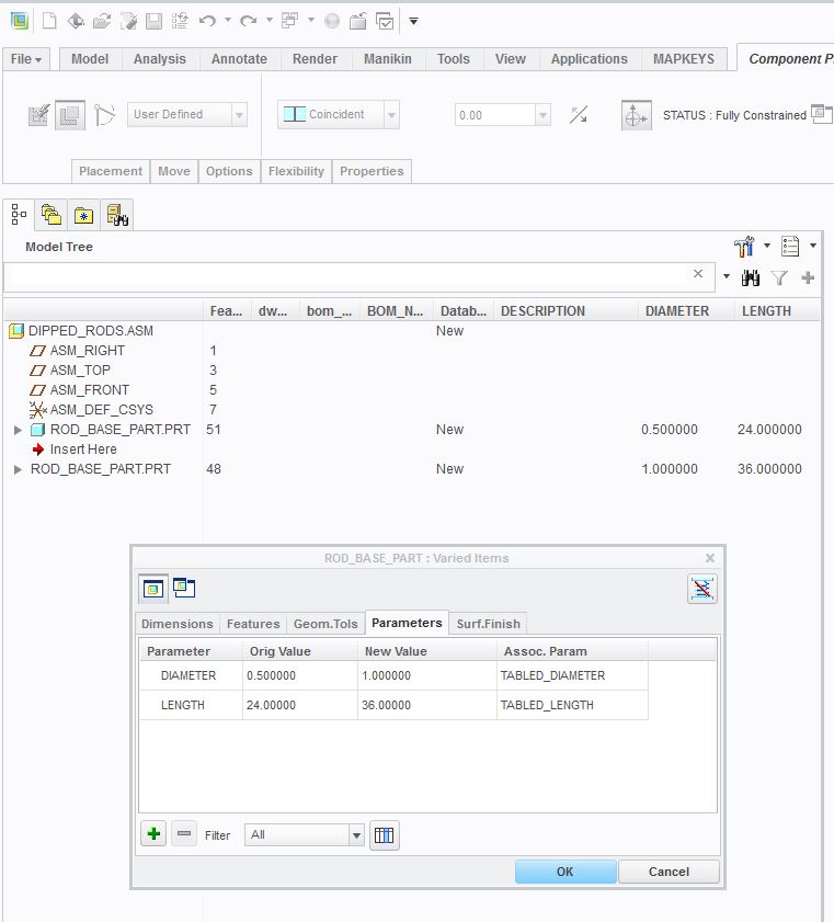
Now I guess I should have seen this coming, but really had been of the understanding that these associated parameters could be family tabled.
However, when I put these parameters into my family table, they do not take on the dimensions for the new instances.
They all stay locked at the new values given for the associated parameters.
In this case 1" and 36"
So, it appears that there is another step somewhere to make this work with family tables.
Any ides?
May 15, 2017
04:57 PM
- Mark as New
- Bookmark
- Subscribe
- Mute
- Subscribe to RSS Feed
- Permalink
- Notify Moderator
Please log in to access translation
May 15, 2017
04:57 PM
Can you explain what you mean by "they do not take on the dimensions for new instances"?
Should they? You didn't explain how you tie value of the parameter to the value of the dimension - did you write a relation at the base part level that makes your "diameter" dimension be equal to the value of the parameter "DIAMETER" ?
But that's a wrong way to go about it anyway; as I recall your application, in your family table instances, you are varying the dimensions of a flexible component's feature. So I think you should be adding the associated parameters to the "dimensions" page of your variable items table (whereas your screenshots show that you added them to the "Parameters" page)...
May 16, 2017
08:08 AM
- Mark as New
- Bookmark
- Subscribe
- Mute
- Subscribe to RSS Feed
- Permalink
- Notify Moderator
Please log in to access translation
May 16, 2017
08:08 AM
As I said, the family table dimensions are simply ignored, and the instances all remain per the new values in the Varied Items - Associated Parameters window.
UPDATED: I got caught up in all of the parts of this, and was so excited to finally understand these Associated Parameters, that I I never wrote the relation, because I don't know how to set the associated parameter to = family tabled values. Everything we have done to this point has been with specific values, per the actual part in the assembly.
If you remember, I did stress several times that I didn't really have a keen understanding of what the Associated Parameters actually do, even though I was finally able to get through your, very helpful and, I must say, very well written exercise, and can now see how they work.
I do theorize, however, that one thing they might be good for, based on the exercise, is to have several copies of a part in an assembly, like maybe a spring, at different compression or tension values.
The family table situation is, again, what I have been trying to get to from the time I started the original post.
Associated parameters were brought into the discussion as the best way to make that happen, and I have been endeavoring to see just how they would work in that usage.
According to you suggestion, here, I don't need associated parameters, but rather, associated dimensions.
How do I write a relation and tell the parameter to = the tabled values?
May 16, 2017
09:48 AM
- Mark as New
- Bookmark
- Subscribe
- Mute
- Subscribe to RSS Feed
- Permalink
- Notify Moderator
Please log in to access translation
May 16, 2017
09:48 AM
I think you are missing the key concept because you think that associated parameters are limited only to the "parameters" page of the flexible component's varied items table. In fact, an associated parameter can be assigned to any varied item, including dimensions.
In your case, for the cylindrical extrusion feature in your "flexible" rod component, you should make two associated parameters - one for the "length" dimension and one for the "diameter" dimension.
Then, in the assembly family table, when you are adding columns, you can add these associated parameters in two ways:
a) select "parameter" as the "type of item to be added", then look in component, pick your flexible rod, and add the two associated parameters from the component's parameter table.
or
b) select "dimension" as the type of item to be varied; as you have already discovered, you will be allowed to select dimensions of features that belong to flexible components.
But this is where your understanding of what the system was doing was quite incorrect, because you thought that you were adding dimensions to your family table, but you were actually adding associated parameters. You didn't realize that the system was creating these associated parameters for you automatically (and I was warning you against this method).
May 16, 2017
10:49 AM
- Mark as New
- Bookmark
- Subscribe
- Mute
- Subscribe to RSS Feed
- Permalink
- Notify Moderator
Please log in to access translation
May 16, 2017
10:49 AM
I remember your warnings very clearly, which is why I am banging my head against the wall endeavoring to come to an understanding of Associated Parameters, so that I might be able to circle back around to those assemblies and modify them to a more stable configuration.
I am beginning to see what is going on here, and the depth of this aspect of CREO.
I will go back and make these alterations to my test assembly and see how it goes.
Funny thing about ProE, Wildfire, CREO, whatever the name, just when you think you have really learned how to use it, another layer of the onion gets peeled, and on and on it goes.
May 16, 2017
11:14 AM
- Mark as New
- Bookmark
- Subscribe
- Mute
- Subscribe to RSS Feed
- Permalink
- Notify Moderator
Please log in to access translation
May 16, 2017
11:14 AM
I know, it took me a long time to understand them. In fact, the discussions I am having with you have increased my own understanding by 100%.
I just want to amend one thing regarding my last posting in this thread.
For method (b), the thing to be avoided is not the picking dimensions of a flexible component as a method of building a family table.
The pitfall to be avoided is doing this without first defining the associated parameters for such dimensions.
May 16, 2017
03:57 PM
- Mark as New
- Bookmark
- Subscribe
- Mute
- Subscribe to RSS Feed
- Permalink
- Notify Moderator
Please log in to access translation
May 16, 2017
03:57 PM
Thank you so much, Paul, for hanging in there with me until my thick head could finally decipher this concept.
--------------------------------------------------------------------
OK, it is all working nicely now.
My base part contains no predefined flexibility.
It does, however, have two added parameters named Diameter and Length.
I have only defined flexibility for the base part as it exists in the assembly.
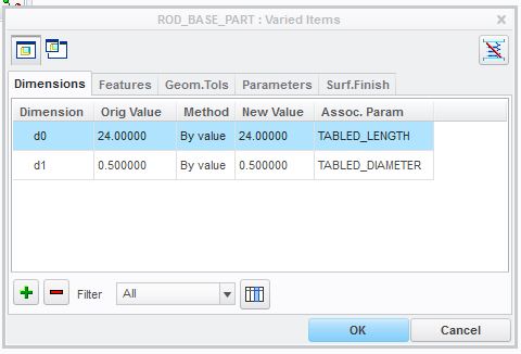
I have set Associated Parameters for part parameters Diameter and Length on the Dimension Page of the Varied Items Window.
I named these Associated Parameters "Tabled_Diameter" and "Tabled Length" as shown below:
Varied Items Window
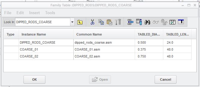
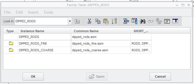
My family table is nested with "Fine" and "Coarse" nested tables.
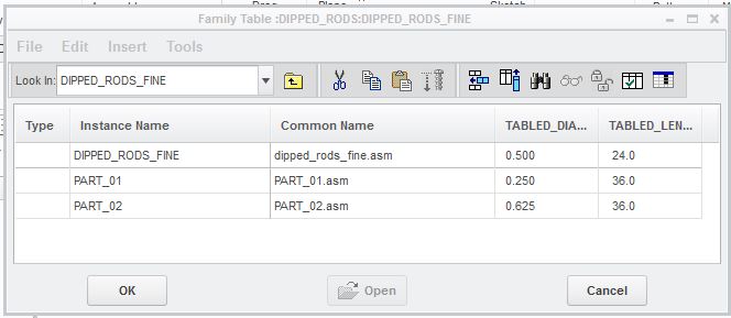
I created two instances in each Nested Family Table, then brought these new Associated Parameters, as columns, into each Nested Family Table.
I then set different dimensions for each instance, again, as shown below:
Now all instances turn out to be the correct Diameter and Length.
I now need to write another set of instructions so that I remember how to do this.
It is, in the end, like most things in ProE, not that complicated. It is however confusing, if you don't do it a bunch relatively often, would most certainly be lost.
Top Level Assembly Family Table
Nested "FINE" Fine Family Table
Nested "FINE" Coarse Family Table